Flow switch
Flow Switch – Working, Types, and Applications
A Flow Switch is a mechanical or electrical device that monitors the flow of air, liquid, or steam in a system. It helps detect whether flow is within the desired range and sends an electrical signal to control devices such as pumps, alarms, or safety interlocks.
Flow switches play a crucial role in preventing equipment damage caused by loss of flow, overheating, or dry running. They are commonly used in water treatment systems, chillers, fire protection, and HVAC systems.
⚙️ Working Principle
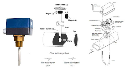
The flow of fluid pushes a paddle or sensor element inside the pipe. This movement changes the position of a mechanical lever or sensor element, activating or deactivating an electrical contact. The signal is then sent to a control system, pump, or alarm circuit.

Construction & typical components
Standard flow switches usually include:
- Body / housing (material matched to fluid)
- Sensing element (paddle, piston, thermal sensor, piezo sensor)
- Mechanical linkage and adjustment (set-point screw or cam)
- Electrical switching element (SPDT/SPST contacts, mercury or microswitch, or solid-state output)
- Connection method (inline threaded, insertion type, or external clamp)
🔍 Types of Flow Switches
- Paddle (Vane ) Flow Switch: Uses a paddle that moves with the fluid. Simple and widely used for water lines. a mechanical paddle protrudes into the flow; economical and reliable for liquids and air.
- Piston (Shuttle) Flow Switch: Measures flow using a spring-loaded piston; suitable for oils and viscous fluids. piston or shuttle movement actuates a contact; suited for oils, high-pressure lines and lubricating systems.
- Thermal Flow Switch: Works on heat transfer — used for gases and clean liquids. senses flow by temperature change of a heated element; often used for leak detection and liquid transfer monitoring.
- Piezoelectric Flow Switch: Uses vibration sensing for precise and compact systems like lubrication control. detects flow/no-flow by sensing vibrations or pressure pulses; useful for spray systems and food processing.
📊 Comparison Table
| Type | Sensing Method | Applications |
|---|---|---|
| Paddle Type | Mechanical displacement | Cooling water, pumps |
| Piston Type | Spring-loaded piston | Oil and lubrication circuits |
| Thermal Type | Temperature variation | Air flow, gas lines |
| Piezoelectric Type | Vibration sensing | Precise low-flow detection |
🧰 Installation Guidelines
- Install on a straight pipe section (10D upstream, 5D downstream).
- Ensure the flow direction matches the arrow on the body.
- Avoid mounting near bends, valves, or pumps to reduce turbulence.
- Use proper sealing to prevent leakage or false signals.
- Regularly inspect and clean the paddle or sensor for debris.
🔌 Wiring Diagram Example

🧠 Common Causes of Wrong Indication
- Air pockets in fluid line
- Improper mounting orientation
- Vibration or turbulence interference
- Debris buildup around the paddle
- Electrical contact failure
❓ Frequently Asked Questions (FAQ)
Q1: What is the difference between a flow switch and a flow meter?
A flow switch detects the presence or absence of flow, while a flow meter measures the exact flow rate.
Q2: Can a flow switch be used for gas?
Yes, thermal and piezoelectric flow switches are suitable for gas or air applications.
Q3: What maintenance is needed?
Clean the sensing element regularly, check electrical contacts, and verify calibration annually.
Q4: How do I test a flow switch?
Simulate flow or manually move the paddle to check continuity using a multimeter.
📘 Applications
Flow switches are used widely for:
- Pump protection — prevent dry running by ensuring minimum flow before pump energization.
- Cooling systems & heat exchangers — ensure adequate coolant flow.
- Fire control systems — verify water flow in sprinkler or deluge systems.
- Process safety — alarm or shut down when flow stops in hazardous ventilation or exhaust lines.
- Chemical dosing & water treatment — confirm dosing pumps are delivering flow.
- Oil well testing, drain line monitoring, relief valve monitoring and many other industrial uses.
Installation & best practices
- Install according to manufacturer orientation and recommended straight-run lengths upstream/downstream.
- Use the manufacturer-supplied fittings and follow torque/pipe prep instructions.
- Avoid locations with trapped air pockets; provide venting where needed.
- Verify set-point and hysteresis for the application; consider adjustable models for fine tuning.
- Periodically inspect paddle and pivot for wear, corrosion or fouling; recalibrate or replace as required.
📧 Email us at: nandantechnicals01@gmail.com
Comments
Post a Comment