Flow Switch | How to Select a Flow Switch as per Line Size | Flow Switch Size calculator.
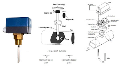
Flow Switch | How to Select a Flow Switch as per Line Size | Flow Switch Size calculator. A flow switch is an instrument used to detect the presence or absence of flow in a pipe or system. Its main purpose is to monitor, control, or protect equipment by triggering an alarm or switching a device ON/OFF when flow conditions change. Definition: A flow switch is a device that detects the presence or absence of flow (liquid, gas, or air) in a pipe and changes a switch state to trigger alarms, control equipment, or protect systems. basically flow switch is a device that activates a switch when liquid, gas, or air starts flowing or stops flowing through a pipeline. How it works A flow switch has a sensing element (paddle, vane, thermal probe, ultrasonic sensor, etc.) and a switch mechanism (mechanical or electronic). When flow crosses a set threshold the switch changes state (ON ↔ OFF) and sends a signal to pumps, alarms, PLCs, or safety interlocks. Common types ...