Elaborate Working of Shell & Tube Heat Exchanger?
Elaborate Working of Shell & Tube Heat Exchanger.
Working of Shell & Tube Heat Exchanger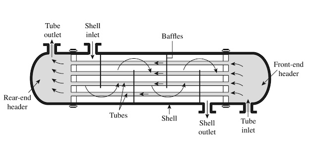

Above figure shows the typical configuration of shell and tube heat exchangers, with labels for easy reading. As previously explained, the fundamental point of shell and tube heat exchangers is to pass a hot fluid through a cold fluid without mixing them, so that only their heat is transferred. The above diagram shows two inlets and two outlets, where each fluid starts at their respective inlet and exits the device at their outlets. The tube-side flow passes through the tube bundle (secured by metal plates known as tubesheets or tubeplates) and exits the tube outlet. Similarly, the shell-side flow starts at the shell inlet, passes over theses tubes, and exits at the shell outlet. The headers on either side of the tube bundle create reservoirs for the tube-side flow and can be split into sections according to specific heat exchanger types.
Each tube contains an insert known as a turbulator which causes turbulent flow through the tubes and prevents sediment depositing, or “fouling”, as well as increases the exchanger’s heat transfer capacity. Designers also cause turbulence in the shell with barriers known as baffles, which maximize the amount of thermal mixing that occurs between the shell-side fluid and the coolant pipes. The shell-side fluid must work its way around these baffles, which causes the flow to repeatedly pass over the tube bundle, thus transferring energy and exiting the heat exchanger at a lower temperature. Certain shell and tube exchangers use differing baffle shapes to maximize heat transfer, and some use none at all.
Shell and tube heat exchangers can be single-phase, or two-phase. A single-phase exchanger keeps the fluid’s phase constant throughout the process (e.g. liquid water enters, liquid water leaves) while a two-phase exchanger will cause a phase change during heat transfer process (e.g. steam enters and liquid water leaves). They can also be single pass or multi pass, which simply describes how many times the tube-side/shell-side flows pass through the device. Figure 1 shows a multi-pass configuration, where the shell-side flow passes over the coolant pipes multiple times before exiting through its outlet. If the baffles were not in Figure 1, then the heat exchanger would be considered a single pass device, as both the tube-side flow and shell-side flow only pass each other a single time.
Comments
Post a Comment