How to test an Op Amp IC?
How to test an Op Amp IC?
Operational Amplifiers are widely used in electronic circuits as amplifiers, comparators, voltage follower, summing amplifier etc. Most of the commonly used Op Amps like 741, TL071, CA3130, CA3140 etc have same pin configurations. Hence this tester is useful to check the working of the Op Amp during trouble shooting or servicing. It is an easy to make tool which is essential in the work bench of a hobbyist or technician.
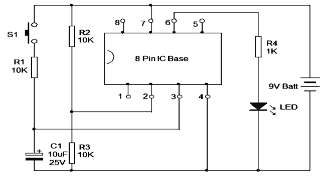
The tester is wired around an 8 pin IC base into which the IC to be tested can be inserted. Pin 2 (inverting input of IC) is connected to a potential divider R2, R3 that gives half supply voltage to pin 2. Pin 3 (None inverting input) of IC base is connected to the VCC through R1 and a Push to on switch. Output pin 6 is used to connect the visual indicator LED via the current limiting resistor R4.
The design is a voltage comparator. Insert the IC in to the socket with correct orientation. The notch at the left side of the IC should match with the notch in the IC base. In this comparator mode, the output of IC1 goes high when its pin 3 gets a higher voltage than pin 2. Here pin 2 gets 4.5 volts (if battery is 9V) and pin 3, 0 volts.
So the output remains low and LED will be dark. When S1 is pressed, pin 3 gets higher voltage than pin 2 and the output of IC turns high to light the LED. This indicates that the circuitry inside the IC is working.

Comments
Post a Comment