Posts

Showing posts with the label Op-amp

Operational Amplifier Fundamentals And Effect Of Feedback In Amplifier Multiple Choice Questions And Answers

Image
  Operational Amplifier Fundamentals And Effect Of Feedback In Amplifier Multiple Choice Questions And Answers 1. Negative feedback in an amplifier a) Reduces gain b) Increase frequency &phase distortion c) Reduces bandwidth d) Increases noise Answer: Reduces gain 2. A differential amplifier has a differential gain of 20,000 . CMRR=80 dB. The common mode gain is given by a) 2 b) 1 c) 1/2 d) 0 Answer: 2 3. The approximate input impedance of the OPAMP circuit which has Ri=10k, Rf=100k, RL=10k a) ∞ b)120k c)110k d)10k Answer: 10k 4. An amplifier using an opamp with slew rate SR=1v/μsec has a gain of 40db.if this amplifier has to faithfully amplify sinusoidal signals from dc to 20 KHz without introducing any slew-rate induced distortion, then the input signal level must not exceed a) 795mV  b) 395mV c) 795 mV  d) 39.5mV Answer: 795 mV   5. An ideal OP-AMP is an ideal a) Current controlled Current source  b) Current controlled voltage source c) Voltage controlled voltage source  d

How to test an Op Amp IC?

Image
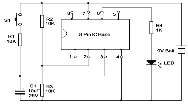
 How to test an Op Amp IC? Operational Amplifiers are widely used in electronic circuits as amplifiers, comparators, voltage follower, summing amplifier etc. Most of the commonly used Op Amps like 741, TL071, CA3130, CA3140 etc have same pin configurations. Hence this tester is useful to check the working of the Op Amp during trouble shooting or servicing. It is an easy to make tool which is essential in the work bench of a hobbyist or technician. The tester is wired around an 8 pin IC base into which the IC to be tested can be inserted. Pin 2 (inverting input of IC) is connected to a potential divider R2, R3 that gives half supply voltage to pin 2. Pin 3 (None inverting input) of IC base is connected to the VCC through R1 and a Push to on switch. Output pin 6 is used to connect the visual indicator LED via the current limiting resistor R4. The design is a voltage comparator. Insert the IC in to the socket with correct orientation. The notch at the left side of the IC should match with

Op-Amp Pin Configuration, Features & Working and Op-Amp IC’s – Pin Configuration, Features & Working

Image
   Operational Amplifier (Op-amp) What is an Operational Amplifier (Op-amp)? An operational amplifier is an integrated circuit that can amplify weak electric signals. An operational amplifier has two input pins and one output pin. Its basic role is to amplify and output the voltage difference between the two input pins. An operational amplifier (op amp) is an analog circuit block that takes a differential voltage input and produces a single-ended voltage output. Pin configuration V+: non-inverting input V−: inverting input Vout: output VS+: positive power supply VS−: negative power supply Operational Amplifier Clasifications There are four ways to classify operational amplifiers: Voltage amplifiers take voltage in and produce a voltage at the output. Current amplifiers receive a current input and produce a current output. Transconductance amplifiers convert a voltage input to a current output. Transresistance amplifiers convert a current input and produces a voltage output. Op-amp ch

Introduction of Active Filter

Image
  Active Filter active filter is a type of analog circuit implementing an electronic filter using active component, typically an amplifier. Amplifiers included in a filter design can be used to improve the cost, performance and predictability of a filter. What is an Active Filter? The filter is an electric n/w in any circuit theory, that used to change either phase or amplitude of signal characteristics with respect to its frequency. Ideally, this will not include any new frequency to the i/p nor it will alter the frequency component of that signal. An Active Filter utilizes an operational amplifiers along with various electronic components like resistors, capacitors for the filtering. Op-Amps are used to allow easily to make many types of active filters.An Amplifier stops the load impedance from affecting the filter characteristics. The form of the response, duality factor and tuned frequency and can often set with inexpensive variable resistors. In these filter circuits we can alter

Operational Amplifier (Op-amp) Characteristics and Applications

Image
    Operational Amplifier (Op-amp) What is an Operational Amplifier (Op-amp)? An operational amplifier is an integrated circuit that can amplify weak electric signals. An operational amplifier has two input pins and one output pin. Its basic role is to amplify and output the voltage difference between the two input pins. An operational amplifier (op amp) is an analog circuit block that takes a differential voltage input and produces a single-ended voltage output. Pin configuration V+: non-inverting input V−: inverting input Vout: output VS+: positive power supply VS−: negative power supply Operational Amplifier Clasifications There are four ways to classify operational amplifiers: Voltage amplifiers take voltage in and produce a voltage at the output. Current amplifiers receive a current input and produce a current output. Transconductance amplifiers convert a voltage input to a current output. Transresistance amplifiers convert a current input and produces a voltage output. Op-amp cha