Posts

Showing posts from April, 2022

Boiler control

Boiler control Boiler control used  Increase uptime and availability The primary objective of most boiler operations is maintaining availability, or uptime. Many facilities have more than one boiler on-site running in parallel. It is essential to maintain and upgrade the boiler control systems to assure steam availability. Modern controls are more reliable and can readily adjust to load swings caused by varying overall plant operations.  Reduce flue gas emissions Failure to comply with current emissions regulations can be as costly as lost utilities. Government mandates enforced by fines, threat of closure, or imprisonment will usually provide sufficient incentive to comply with the regulations and modernize controls if necessary. Improved combustion efficiency reduces unwanted combustion by-products. Anything that goes into the manufacture of a product (raw materials, fuel, air, water, etc.) that is not in the final product is wasted cost. This can also create added waste disposal pro

Boiler steam pressure control

Boiler steam pressure control Steam pressure is the key variable that indicates the state of balance between the supply and demand for steam.  If supply exceeds demand, the pressure will rise.  A steam flow feedforward signal is used with steam pressure control.

Boiler Master Control

Boiler Master Control  With several boilers supplying a common header in parallel, it is generally desirable to provide a way to adjust the load distribution among the boilers. Depending on the load and the performance of the individual boilers, the most efficient operation may be achieved with some boilers shut down, some boilers base loaded (constant firing rate), and the remaining boilers allowed to swing with the load (variable firing rate).

Furnace Pressure control

Furnace Pressure control  A basic boiler has a steam water system and a fuel-air flue gas system.  In the fuel-air-flue gas system, the air and fuel are mixed and ignited in the furnace.  Air and fuel flow into the furnace and flue gas flows out.  The force driving this flow is the differential pressure between the gases inside the  furnace and those outside the furnace.  Furnace pressure is commonly referred to as draft or draft pressure.  The draft is maintained slightly negative to prevent the combustion products and ash  from being discharged from the furnace into surrounding areas through inspection ports,  doors, feeders, etc.  For greatest efficiency, the controlled pressure should be as close as possible to  atmosphere, thereby minimizing the ingestion of "tramp air" or excess air drawn through  the openings in the furnace duct work that cool combustion gases.  Furnaces are classified by the method for moving air and other gases through the  system.

Superheater

Superheater It is used to remove the moisture from saturated steam coming out of boiler to increase its temperature above saturation point It avoids condensation of steam and avoids the erosion of blades in turbine The metal used for super heat tubes must have high temperature strength, creep strength and resistance to oxidation Normally carbon steel and chromium Molybdenum alloys are used they withstand temperature of 510ºC and 650 ºC Temperature of combustion is approaching the fusing temperature of ash in the coal and therefore there is tendency of the ash to collect in the fluid form on superheat tubes. This is called as slagging. Methods to avoid slagging Locate close to the furnace to develop required steam temperature A bank of screen tubes before superheater to limit slag accumulation Limiting constant temperature of 60 to 65% of load rating Use of combined convection-radiation superheater It effects improvement and economy in the following ways The super heater increases the c

Oil Pressure Drop Relay

Oil Pressure Drop Relay This is a device designed to monitor a process pressure and provide an output when a set pressure (setpoint) is reached. A pressure switch does this by applying the process pressure to a diaphragm or piston to generate a force which is compared to that of a pre-compressed range spring. A pressure switch is used to detect the presence of fluid pressure. Most pressure switches use a diaphragm or bellow as the sensing element. The movement of this sensing element is used to actuate one or more switch contacts to indicate an alarm or initiate a control action. Pressure switches have different designs with different sensing elements. One of the most common is the one with diaphragms or bellows as the sensing elements The one I will discuss here uses a piston as the pressure sensing element. In any case, the operating principle for this piston type is the same with a diaphragm or bellow type pressure switch.

Turbine Classification

Turbine Classification  The turbines may be classified based on the process condition, they are Condensing turbine Non-Condensing turbine Extraction turbine Condensing turbine The input to the turbine may be from a single source or from a number of boilers connected to a steam bus and then supplied The output may be condensing in which the exhaust pressure is sub-atmospheric (vacuum) The condensed water is recirculated back into feed water stream to avoid treatment of more freshwater Here the makeup water requirement is kept at minimum Non-Condensing turbine The input to the turbine is similar to that of condensing turbine, but the output may be ‘non-condensing’ in which the exhaust pressure is greater than atmospheric Such a turbine is also called backpressure turbine The steam that exhausted with some pressure may be utilized as process steam for other purposes in the plant Such a steam is called process steam or intermediate pressure steam or low pressure steam Extraction turbine Bo

Steam Turbines

Steam Turbines  A steam turbine converts the energy of high-pressure, high temperature steam produced by a steam generator into shaft work. The energy conversion is brought about in the following ways The high-pressure, high-temperature steam first expands in the nozzles emanates as a high velocity fluid stream. The high velocity steam coming out of the nozzles impinges on the blades mounted on a wheel. The fluid stream suffers a loss of momentum while flowing past the blades that is absorbed by the rotating wheel entailing production of torque. The moving blades move as a result of the impulse of steam (caused by the change of momentum) and also as a result of expansion and acceleration of the steam relative to them. In other words they also act as the nozzles. A steam turbine is basically an assembly of nozzles fixed to a stationary casing and rotating blades mounted on the wheels attached on a shaft in a row-wise manner. Steam turbines are employed as the prime movers together with

Boiler Drum Level (Feedwater) Control

Boiler Drum Level (Feedwater) Control The cylindrical vessel where the water-steam interface occurs is called the boiler drum. Boiler drum level is a critical variable in the safe operation of a boiler. A low drum level risks uncovering the water tubes and exposing them to heat stress and damage. High drum level risks water carry over into the steam header and exposing steam turbines to corrosion and damage. The level control problem is complicated by inverse response transients known as shrink and swell. Simply put, shrink and swell refer to a decreased or an increased drum level signal due to the formation of less or more vapor bubbles in the water, and no change in the amount of water in the drum. This condition produces level changes during boiler load changes in the opposite direction of what is expected with a particular load change. Although only temporary, this can cause severe control system overshoot or undershoot.  Benefits of Boiler Drum Level Control Maximizes steam qualit

Boiler steam temperature control

Boiler steam temperature control Accurate steam temperature control is necessary for avoiding the over stressing of superheater tubes and turbine front stages and to maintain overall efficiency as high as possible. Heating the steam further from saturation temperature is called superheating. Saturated steam from the boiler is passed through superheaters, where the heat energy from combustion gases is added to it to generate superheated steam. Water side steam temperature control Desuperheater Attemperator Diverting part of the feed water through attemperator for condensing partially saturated boiler steam Fire side steam temperature control Excess air control Flue gas bypass control Adjustable / tilting burner control  Water side steam temperature control Desuperheater action is just reverse of superheater action. The temperature and heat content of steam is reduced here unlike the superheater which increases the temperature and heat content of steam. Desuperheater may be located eithe

Combustion control

Combustion control The primary function of combustion control is to deliver air and fuel to the burner at a rate that satisfies the firing rate demand and at a mixture (air/fuel ratio) that provides safe and efficient combustion. Insufficient air flow wastes fuel due to incomplete combustion and can cause an accumulation of combustible gases that can be ignited explosively by hot spots in the furnace. Too much air flow wastes fuel by carrying excess heat up the stack. Combustion controls are designed to achieve the optimum air/fuel ratio, while guarding against the hazard caused by insufficient air flow.  

Excess air in boiler

Excess air in boiler  Excess air means that amount of air supplied in addition to the theoretical quantity necessary for complete combustion of all fuel or combustible waste material present. Excess air ensures that there is enough air for complete combustion.  Excess air is expressed as a percentage of theoretical air required. Thus, 10% excess air indicates that 110% total air is being supplied.  In boiler operation, excess air represents a heat loss. This loss must be balanced against losses from incomplete combustion. Boiler efficiency is highly dependent on the excess air rate. So operators should optimize excess air to increase system efficiency. To ensure combustion is complete, they also should provide more combustion air than theoretically is required for boilers. This tactic helps ensure safe boiler operation. Technicians also should keep excess air levels as low as possible about 15 percent excess air, equivalent to 3 percent oxygen to reduce the quantity of air to be heated

Non return valve

Non return valve A non-return valve allows a medium to flow in only one direction and is fitted to ensure that the medium flows through a pipe in the right direction, where pressure conditions may otherwise cause reversed flow. There are different types of non-return valves, such as spring-loaded, swing type, and clapper type valves. Non-return valves are for example used with mixing loops in heating and cooling systems to ensure proper operation, and with domestic water systems to prevent backflow.  Non return valves basically allow the flow to move in just one direction. As a result, they’re also known as one-way valves. NRVs are also considered a kind of two-port valve as they have two openings: One opening is for exiting and the other is for entering fluids. NRVs usually don’t require manual assistance and function automatically. So most NRVs don’t have stems or handles. Types of Non-Return Valve Lift Check Valve Swing Check Valve Folding Disc Check Valves Tilting Disc Check Valve

Integrated Building Management System

Integrated Building Management System IBMS stands for Integrated Building Management System. An Integrated Building Management System is a single, comprehensive building management system for HVAC, lighting, security, fire and other systems. The Building Management System (BMS) can be defined as the system installed in buildings that controls and monitors the building’s mechanical and electrical equipment, such as heating, cooling, ventilation, and lighting. These systems typically represent 70% of a building's energy usage. Obviously, the role of BMS is crucial in management of the building’s energy demand. Beyond controlling the internal environment of the building, the IBMS (Integrated Building Management System) covers also access control, intruder alarms, video surveillance, monitoring of fire alarm system and other systems as applicable. IBMS can be referred to as the Integrated BMS and Security System the single, uniform system for building management. Application of full IB

BMS Alarms and security

BMS Alarms and security All modern building automation systems have alarm capabilities. It does little good to detect a potentially hazardous or costly situation if no one who can solve the problem is notified. Notification can be through a computer (email or text message), pager, cellular phone voice call, audible alarm, or all of these. For insurance and liability purposes all systems keep logs of who was notified, when and how. Alarms may immediately notify someone or only notify when alarms build to some threshold of seriousness or urgency. At sites with several buildings, momentary power failures can cause hundreds or thousands of alarms from equipment that has shut down – these should be suppressed and recognized as symptoms of a larger failure. Some sites are programmed so that critical alarms are automatically re-sent at varying intervals. For example, a repeating critical alarm (of an uninterruptible power supply in 'bypass') might resound at 10 minutes, 30 minutes, an

Hot water system in BMS

Hot water system in BMS The hot water system supplies heat to the building's air-handling unit or VAV box heating coils, along with the domestic hot water heating coils. The hot water system will have a boilers and pumps. Analog temperature sensors are placed in the hot water supply and return lines. Some type of mixing valve is usually used to control the heating water loop temperature. The boilers and pumps are sequenced on and off to maintain supply.

Chilled water system in BMS

Image
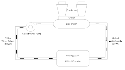
Chilled Water System in BMS Chilled water is used to cool the building's air and equipment. A chilled water system consists of chillers and pumps. Analog temperature sensors measure the cooling water supply and return lines. Chillers are switched on and off to cool the chilled water supply. A chiller is a refrigeration unit designed to produce chilled (cold) water for space cooling purposes. The cooled water is then circulated to one or more cooling coils located in air handling units, fan-coils or induction units. Cooling water distribution is not limited by the 100 foot separation limit that applies to DX systems, thus cooling systems based on chilled water are used in larger buildings. Capacity control in chilled water systems is usually achieved by modulation of water flow through the coil; Thus, multiple coils can be fed from a single chiller without compromising control of any individual unit. Chillers can work on vapor compression principle or absorption principle. Vapor com

BMS Air handlers

BMS Air handlers Most air handlers mix return and outside air so less temperature/humidity conditioning is needed. This can save money by using less chilled or heated water (not all AHUs use chilled/hot water circuits). Some external air is needed to keep the building's air healthy. To optimize energy efficiency while maintaining healthy indoor air quality (IAQ), demand control (or controlled) ventilation (DCV) adjusts the amount of outside air based on measured levels of occupancy. Analog or digital temperature sensors may be placed in the space or room, the return and supply air ducts, and sometimes the external air. Actuators are placed on the hot and chilled water valves, the outside air and return air dampers. The supply fan (and return if applicable) is started and stopped based on either time of day, temperatures, building pressures or a combination. Constant volume air-handling units The less efficient type of air-handler is a constant volume air handling unit or CAV. The f

BMS Controllers

BMS Controllers BMS Controllers are purpose-built computers with input and output capabilities. These controllers come in a range of sizes and capabilities to control devices commonly found in buildings and to control sub-networks of controllers. Inputs allow a controller to read temperatures, humidity, pressure, current flow, air flow, and other essential factors. The outputs allow the controller to send command and control signals to slave devices, and to other parts of the system. Inputs and outputs can be either digital or analog. Digital outputs are also sometimes called discrete depending on manufacturer. Controllers used for building automation can be grouped in 3 categories. Programmable Logic Controllers (PLCs), System/Network controllers, and Terminal Unit controllers. However an additional device can also exist in order to integrate 3rd party systems (i.e. a stand-alone AC system) into a central Building automation system).System/Network controllers may be applied to control

Communication of a BMS

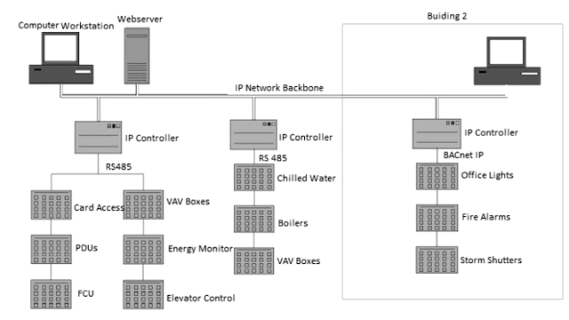
Communication of a BMS Buses and protocols Most building automation networks consist of primary and secondary buses which connect high-level controllers with lower-level controllers, input/output devices and a user interface devices. ASHRAE's open protocol BACnet or the open protocols LonTalk specify how most such devices interoperate. Modern systems use SNMP to track events, building on decades of history with SNMP (Simple Network Management Protocol)-based protocols in the computer networking world. Physical connectivity between devices was historically provided by dedicated optical fiber, ethernet, ARCNET, RS-232, RS-485 or a low-bandwidth special purpose wireless network. Modern systems rely on standards-based multi-protocol heterogeneous networking. These accommodate typically only IP-based networking but can make use of any existing wiring, and also integrate power line networking over AC circuits, power over Ethernet low power DC circuits; high-bandwidth wireless networks su

Building Management System

Image
Building Management System A Building Management System (BMS), otherwise known as a Building Automation System (BAS), is a computer-based control system installed in buildings that controls and monitors the building's mechanical and electrical equipment such as ventilation, lighting, power systems, fire systems, and security systems. A BMS consists of software and hardware; the software program, usually configured in a hierarchical manner, can be proprietary, using such protocols as C-Bus, Profibus, and so on. Vendors are also producing a BMS that integrates the use of Internet protocols and open standards such as Device Net, SOAP, XML, BACnet, Lon Works and Modbus The Building Automation System (BAS) core functionality is to keep building climate within a specified range, light rooms based on an occupancy schedule, monitor performance and device failures in all systems and provide malfunction alarms. Automation systems reduce building energy and maintenance costs compared to a non

Building Automation Systems

Building Automation Systems Building automation systems are like one half of a building’s brain. They’re the part that tells equipment around the building what to do, the same way that your brain tells your fingers what to do. (The other half of the brain, the part that handles incoming sensory information, is analogous to an energy management system.) A building automation system operates the controls of a building from a central hub, though many modern systems can be remotely controlled through a digital platform or app. The software at the heart of this type of system operates using a logic algorithm to manage controls according to direct inputs and preset conditions, giving rise to the term “smart building or Intelligent building.” A building automation system, or BAS as it is commonly abbreviated, networks and controls almost every major element of a space. A short list of systems automated in the typical smart building might include the following Lighting and other electrical sys

Coriolis Flow Meter

Image
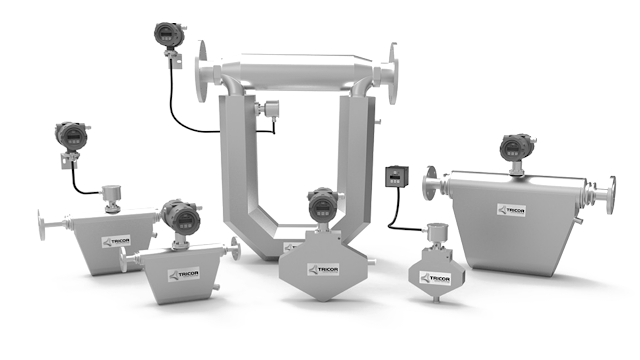
Coriolis Flow Meter A Coriolis flow meter measures mass by the inertia of a liquid or gas flowing through a vibrating tube that is equipped with a set of sensors at the inlets and outlets of the meter. The increased movement of the flow produces measurable oscillation that is proportional to the mass. The design and function of Coriolis flow meters has made them the most reliable form of fluid and gas measuring instruments. Types for Coriolis Flow Meters Single Tube Flow Meter Dual Tube Flow Meter Continuous Loop Flow Meter Straight Tube Flow Meter U Shaped Flow Meter Micro-Bend Flow Meter Triangle Shaped Flow Meter Single Tube Flow Meter The single tube design measures high fluid velocity that is created by reducing the cross sectional area in relation to the pipe. Tube distortion is measured in relation to a fixed point or plane. The tube is excited at a high amplitude bending force that is created at an anchored point. Dual Tube Flow Meter In the dual tube design of a Coriolis flo

Components of fire Alarm system

Components of fire Alarm system Basic Fire Alarm System Components Fire alarm initiating devices Fire notification devices Fire alarm control panel Primary power supply Backup power supply Fire Alarm Initiating Devices The role of the alarm initiating devices in a fire alarm system is to activate the system when a fire occurs. There are two types of fire alarm initiating devices are  Manual initiating devices Automatic initiating devices Manual initiating devices Manual initiating devices need to be well marked and accessible to make it easy to identify and use. These devices include pull stations, break glass stations or buttons that need to be manually activated by someone in the building when they identify a fire.  Automatic initiating devices Automatic initiation devices trigger the fire alarm system automatically when a fire happens. These devices include heat, flame and smoke detection. When heat, flames or smoke is detected, the devices send a signal to a central control panel t

Components of fire detection system

Components of fire detection system At the core of a fire alarm system are the detection devices, from sophisticated intelligent smoke detectors to simple manually operated break glass units, there are a wide array of different types, but we can divide them into groups including Heat detectors Smoke detectors Carbon Monoxide detectors Multi-sensor detectors Manual Call Points Heat Detectors Heat detector can either work on a fixed temperature basis, where it will trigger an alarm if the temperature exceeds a pre-set value or they can work on the rate of change in temperature. Commonly Heat detectors work in a similar way to an electrical fuse, the detectors contain a eutectic alloy which is heat sensitive when a certain temperature is reached the alloy turns from a solid to a liquid which in turn triggers the alarm. Smoke Detectors There are three basic types of smoke detectors including Ionization Light Scattering Light Obscuring Ionization Smoke Detector Ionization Smoke detector gen

Fire alarm systems

Fire alarm systems Fire alarm systems save lives and protect property. Fire alarm systems also break down because they are electrical. Class A or Class B wiring loops help the fire alarm panel to find these breakdowns (faults) before a fire, while there is time for repairs. Class B Loops In conventional Class B Loops, all devices are daisy-chained together. Bypassing a small electrical current passing through the wires, the panel supervises them, and to limit this supervising current, at the end of the daisy-chain is an end-of-line resistor. The panel constantly watches for this current.  Open Fault in the Class B wiring. Supervision tells the panel that the wiring does not go through, but also the devices further from the panel don't work. If the supervising currentstops flowing, the panel assumes a wire is broken (an open fault), and displays a trouble. When a wire breaks in Class B, the devices closest to the panel will still work, but because of the wire break, the devices furt