Posts

Showing posts with the label IA

Introduction to Industrial Measurement

Introduction to Industrial Measurement Various types of control systems and instruments are used in industry to complete the process and basically to measure and calibrate the process. Simple industrial measurements are fluid pressure, fluid flow, system or object temperature, environmental temperature, fluid volume, chemical concentration, system acceleration, device speed or position, object physical diameter and device voltage, current, resistance, etc. Fluid Pressure Measurement: This parameter measures the pressure of a fluid or object using various types of devices or sensors. And there are two types of this measurement manual measurement and automatic measurement. A common automatic gauge is used to measure fluid pressure and a differential pressure sensor is used in this measurement. Fluid Flow Rate: The this parameter measures the fluid flow throughout a pipe or object, and the this measurement uses a variety of sensors to measure fluid flow. And generally measure this parame

Hazard and Risk

Image
Hazard and Risk  Hazard A hazard is "an inherent physical or chemical characteristic that has the potential for causing harm to people, property, or the environment”. In chemical processes: “It is the combination of a hazardous material, an operating environment, and certain unplanned events that could result in an accident”. Hazard is the potential for harm. A hazard is often associated with a condition or activity that can cause undesired consequences such as injury or illness if left uncontrolled. Basically, a hazard can cause harm or adverse health effects to individuals or to organizations as property or equipment losses. Types of hazard Chemical hazards Physical hazards Biological hazards (biohazards) Ergonomic hazards Noise hazards Chemical hazards Chemicals can affect skin by contact. Chemicals can also enter our body either through the inhalation or digestive system if air is contaminated with chemicals, vapor, mist or dust. The accumulation of chemicals in or on our body

Hazard & Operability study (HaZOP)

Image
Hazard & Operability study (HaZOP) Hazard & Operability study Also called HaZOP Determination of deviation from their design basis Diagrams of the facility’s piping, electrical system and instrumentation can be used The hazard and operability (HAZOP) study is the most commonly used process hazard analysis (PHA) method in the world today. Originated as a hazard identification technique for process plants commonly applied in petrochemical, nuclear and food processing industries. Described as a system of imaginative anticipation of hazards. Always a team activity. Concentrates on deviations in flows between components. Uses well-defined guide words to steer analysis. Considers both plausible causes and possible consequences of deviations. The flowchart in the figure illustrates the process of conducting a HAZOP study

Process Hazard Analysis (PHA)

Image
Process Hazard Analysis (PHA) Anticipates events based on the chemicals used in storage and processes To preclude uncontrolled releases or to minimize their severity if released A method to determine plant or process chemical hazards and develop policies, procedures and safeguards against emergencies which may occur. A process hazard analysis (PHA) (or process hazard evaluation) is a set of organized and systematic assessments of the potential hazards associated with an industrial process. A PHA provides information intended to assist managers and employees in making decisions for improving safety and reducing the consequences of unwanted or unplanned releases of hazardous chemicals. A PHA is directed toward analyzing potential causes and consequences of fires, explosions, releases of toxic or flammable chemicals and major spills of hazardous chemicals, and it focuses on equipment, instrumentation, utilities, human actions, and external factors that might impact the process.

Advantages of implementing SCADA system for electrical distribution

Advantages of implementing SCADA system for electrical distribution  A SCADA system for a power distribution application is a typically a PC-based software package. Data is collected from the electrical distribution system, with most of the data originating at substations. Depending on its size and complexity, a substation will have a varying number of controllers and operator interface points. In a typical configuration, a substation is controlled and monitored in real time by a Programmable Logic Controller (PLC) and by certain specialized devices such as circuit breakers and power monitors. Data from the PLC and the devices is then transmitted to a PC-based SCADA node located at the substation. Benefits of Implementing SCADA systems for Electrical Distribution Increases reliability through automation Eliminates the need for manual data collection Alarms and system-wide monitoring enable operators to quickly spot and address problems Automation protects workers by enabling problem

HMI

HMI  HMI (Human Machine Interface) is a device or software that is used to communicate with the machines or groups of machines in the plant or production area. HMI is mainly used for, To monitor or visualize the process To control the process To visualize trends, alarms, etc. HMI may come in the form of the built-in screen on machines, computers, tablets, etc. but after all these forms the purpose is the same as an interacting human with machines.

PLC SCADA Relationship

PLC SCADA Relationship PLCs are a part of the system that SCADA oversees. The PLCs need SCADA to control their function, but SCADA relies on data from the PLCs to complete its overview. PLC SCADA relationship is invariably powerful in creating an automated system to accurately prescribe maintenance tasks. For example, if used to monitor a turbine, the PLC may collect data that suggests there is too much vibration in the system. The PLC will transmit that data back to the SCADA software. SCADA will analyze the readouts and determine whether or not an adjustment needs to be made to the system. If a change must be made, SCADA transmits the changes back through the PLCs to facilitate the correction.

SCADA Types, Functions, SCADA System Architecture, Benefits and Applications

Image
SCADA Types, Functions, SCADA System Architecture, Benefits and Applications SCADA SCADA is the short abbreviation of Supervisory Control and Data Acquisition. As the name suggests SCADA mainly does three operations Supervise real-time data in the form of graphical presentation Control industrial processes locally or through Remote locations Acquire real-time data as well as logs data SCADA system is an important factor of the industrial organization as they help to monitor process data as well as control the processes and easily detect any issue within the process thus reduce downtime. Generally, SCADA is completely a software package that helps to monitor the entire area of the plant. The basic architecture of the SCADA begins with a Programmable Logic Controller(PLC) or Remote Terminal Units(RTUs). As we know, PLC or RTUs are microprocessors that communicate with the field devices such as valves, pumps, sensors, HMIs, other end devices, etc. These devices route all this collected da

RS-232

RS-232 It is basically a interface standards. It is commonly used in computer serial ports. The standard defines the electrical characteristics and timing of signals. The current version of the standard is TIA In RS-232, user data is sent as a time series of bits. Both synchronous and asynchronous transmissions are supported by the standard. RS-232 devices may be classified as Data Terminal Equipment (DTE) or Data Communication as modems, that are responsible for data transferring Equipment (DCE), this defines that each device which wires will be sending and receiving each signal. DTE refers to terminals and computers that sends and receives data. DCE refers to communication equipment. An RS-232 serial port was once a standard feature of a personal computer, used for connections to modems, printers, mouse, data storage, uninterruptible power supplies, and other peripheral device

RS-485

RS-485 RS-485 is a EIA standard interface which is very common in the data acquisition world RS-485 provides balanced transmission line which also can be shared in Multi-drop mode. It allows high data rates communications over long distances in real world environments. RS-485 was designed for greater distance and higher baud rates than RS-232. According to the standard, 100kbit/s is the maximum speed and distance up to 4000 feet(1200 meters) can be achieved.

safety Integrity Level (SIL)

Image
Safety Integrity Level (SIL)  Safety Integrity Level is also known as SRS (Safety Related System). A safety integrity level is an appropriate system. The safety integrity level reduces the risk of devices under control (EUC). Uses one or more safety systems to reduce risk. Functional safety (FS) requires safety function and safety integrity A safety integrity level covers all safety lifecycle activities. As SIL provides FS (Functional Safety), SIL specifies target levels of risk reduction, SIL measures SIF (Safety Instrumented Function). A safety integrity level (SIL) is defined as the relative level of risk-reduction provided by a safety function or specifies a target level of risk reduction. As such, SIL is a measure of the performance required for the Safety Instrumented Function (SIF). In functional safety standards based on the IEC 61508 standard, four SILs are defined as SIL 4, SIL 3, SIL 2 and SIL 1, with SIL 4 being the most reliable and SIL 1 the lowest. Several methods are us

Safety Instrumented System (SIS)

Image
Safety Instrumented System (SIS) A safety instrumented system consists of sensors, logic solvers, and final control elements that are all separate from the basic process control system elements, and the logic solver directs the final control elements to the state required to provide a safe state if the input indicates an abnormal condition. Safety instrumented systems are used to monitor the status of plant values ​​and parameters within operational limits and when a risk situation occurs, they should trigger an alarm and also put the plant in a safe state or shutdown state. Safety instrumented systems are control systems that detect inherently dangerous conditions and bring the process to a safe state. A Safety Instrumented System (SIS) protects the environment from harm caused by specified hazardous conditions. When applied to a specific situation SIS is generally viewed as a separate control system that operates independently of any other controls or individuals. A safety instrument

Emergency Shutdown System (ESD System)

Emergency Shutdown System (ESD System) Emergency shutdown system or ESD is a system that is used in hazardous areas to prevent situations that could have catastrophic effects economically, environmentally, or operationally. They are designed to minimize the consequences of emergency situations, such as injury to personnel or damage to equipment, by protecting against things like leaks, escape of hydrocarbons, fire outbreaks, and explosions. Emergency shutdown systems can be found on oilfields (oil well heads), oil and gas processing plants, gas and steam turbine power plants, and boilers.  Emergency shutdown systems work Emergency shutdown systems work by determining when there is a critical condition within a system and then activating to quell possible leaks, explosions, or other types of major malfunctions.  The activation of an ESD may include Shut down of part systems and equipment Isolation of hydrocarbon inventories Isolation of electrical equipment Depressurization or blowdown

Logical Function Blocks available in DCS

Image
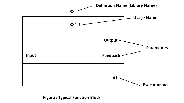
Logical Function Blocks available in DCS  Generally in DCS Functional Block Diagram (FBD) is used for programming and Sequential Flow Charts (SFC) is preferred for batch control applications. Functional Block Diagram (FBD) This language basically is a graphical language wherein the users are allowed to program elements in the form of blocks. The blocks then can be wired together like electrical circuits. It describes a function between input and output variables. It is a graphical method of programming DCS. Functional algorithms and control strategies for a particular plant can be implemented by FBD. The control modules are treated as unique entity in DCS system. Each function block contains specific algorithm such as AI, AO, DI, DO, PID and the parameters required for the algorithm. Function blocks ranges from simple input conversion block to a complex control strategy. Generally available Function blocks are Input/ Output (I/O) Math Logical Timer/ Counter Analog Control Advanced cont

Difference between PLC and DCS

Image
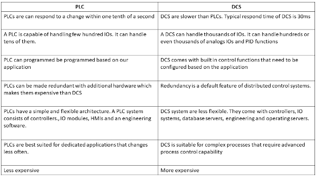
Difference between PLC and DCS PLC  PLCs are can respond to a change within one tenth of a second DCS DCS are slower than PLCs. Typical respond time of DCS is 30ms PLC  A PLC is capable of handling few hundred IOs. It can handle tens of them. DCS A DCS can handle thousands of IOs. It can handle hundreds or even thousands of analogs IOs and PID functions PLC  PLC can programmed be programmed based on our application DCS DCS comes with built in control functions that need to be configured based on the application PLC  PLCs can be made redundant with additional hardware which makes them expensive than DCS  DCS Redundancy is a default feature of distributed control systems. PLC  PLCs have a simple and flexible architecture. A PLC system consists of controllers., IO modules, HMIs and an engineering software.  DCS DCS system are less flexible. They come with controllers, IO systems, database servers, engineering and operating servers. PLC  PLCs are best suited for dedicated applications that

PLC VS SCADA

Image
PLC VS SCADA

What is Structured Text Programming?

Structured text Structured Text is a programming language and is primarily designed for PLCs and Structured Text is ST or STX. Structured Text Language is the simplest language of PLC and this language does not need to be written for PLC programming background. And this language does not require PLC programming software to create structured text programs. Basically structured text is a text based language in which this language writes a simple text file and copy and paste into the PLC project. Structured text languages ​​have common advantages Text based language Light language No programming background required Cost effective What is Structured Text? Structured Text is the programming language of PLC and is a text based language. Basically structured text is known as ST or STX. What is the use of structured text? Basically the use of structured text is to program the PLC.

PWM

PWM  PWM is pulse width modulation Pulse width modulation reduces the average power delivered by an electrical signal by converting the signal into discrete parts. In the PWM technique, the signal’s energy is distributed through a series of pulses rather than a continuously varying (analog) signal Pulse width modulation or PWM is a commonly used control technique that generates analog signals from digital devices such as microcontrollers.

Ladder logic for controlling the running state of the single phase motor by pressing START and STOP pushbuttons

Image
Ladder logic for controlling the running state of the single phase motor by pressing START and STOP pushbuttons

PTO function used in PLC systems

PTO function used in PLC systems   PTO (Pulse Train Output) PTO is for accurate positioning or precise velocity-control. A pulse rotates the motor by a fractional amount. Changing of frequency while duty cycle remains at 50%. T (duration) is varied. The control is done from software. The ratio of T (OFF) to T (ON) can be fixed at 50%:50%. Motion control: The open loop control of stepper motor the stepper motor amplifier ensures a constant distance increment for each pulse received. The duration of the increment is given by the frequency of the pulse. This is more familiar to use than PWM, used for stepper motors and servo motors. Position and speed can be controlled even if only open loop control is used. The Programmable Logical control provides for motion control. With the S7-1200 FW4.2 a new block is available that can set the frequency. A user program can manipulate directly the frequency. This is helpful for working speed control of variable speed drives instead of using analog co