Posts

Showing posts with the label CSD

Root Locus Effect of Addition of zeros

Image
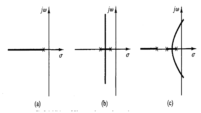
Root Locus Effect of Addition of zeros Addition of zeros The addition of a zero to the open-loop transfer function has the effect of pulling the root locus to the left, tending to make the system more stable and to speed up the settling of the response.  Physically, the addition of a zero in the feed forward transfer function means the addition of derivative control to the system. The effect of such control is to introduce a degree of anticipation into the system and speed up the transient response. The Figure 1(a) shows the root loci for a system that is stable for small gain but unstable for large gain.  Figures 1(b), (c), and (d) show root-locus plots for the system when a zero is added to the open-loop transfer function. It becomes stable for all values of gain. However, it is not possible to add an isolated zero to a transfer function because of physical non-realizability. Therefore, in order to realize the compensating network a pair of pole-zero has to be incorporated.

Root Locus Effect of Addition of zeros and poles

Image
Root Locus Effect of Addition of zeros and poles Addition of zeros The addition of a zero to the open-loop transfer function has the effect of pulling the root locus to the left, tending to make the system more stable and to speed up the settling of the response.  Physically, the addition of a zero in the feed forward transfer function means the addition of derivative control to the system. The effect of such control is to introduce a degree of anticipation into the system and speed up the transient response. The Figure 1(a) shows the root loci for a system that is stable for small gain but unstable for large gain.  Figures 1(b), (c), and (d) show root-locus plots for the system when a zero is added to the open-loop transfer function. It becomes stable for all values of gain. However, it is not possible to add an isolated zero to a transfer function because of physical non-realizability. Therefore, in order to realize the compensating network a pair of pole-zero has to be incorporated.

Types of Compensator

Image
Types of Compensator   Series Compensator   Connecting compensating circuit between error detector and plants known as series or cascade compensation Feedback Compensator   Feed forward Compensator Types of Series Compensator  There are three different types of series compensator  Lead compensator Lag compensator Lag-lead compensator Lead compensator   The lead compensator in a control system produces the output with a phase lead. Here, lead means ahead. It is a type of successor activity. It consists of a two resistors, named as R1 and R2, and one capacitor C. The transfer function of a system is given by Transfer function = Output/ Inpute  The output of the lead compensator diagram is an RC circuit, and it depicts that the output is connected across the second branch. It has only one resistor, R2. So, the output of the circuit is R2. Vo(s) = R2 Let's find the input. The input will be the series or parallel combination of the elements (capacitor and resistors). The resistor R1 is

Control Systems MCQ

Control Systems MCQ 1. The transfer function technique is considered as inadequate under which of the following conditions ? a) Systems having complexities and non-linearities b) Systems having stability problems c) Systems having multiple input dis¬turbances (d) All of the above Answer: All of the above 2. With feed back ____________ reduces. a) system stability b) system gain c) system stability and gain d) none of the above Answer: system gain 3. Which of the following is the output of a thermocouple ? a) Alternating current b) Direct current c) A.C. voltage d) D.C. voltage Answer: D.C. voltage 4. Which of the following is exhibited by Root locus diagrams ? a) The poles of the transfer function for a set of parameter values b) The bandwidth of the system c) The response of a system to a step input d) The frequency response of a system Answer: The poles of the transfer function for a set of parameter values 5. If the gain of the critical damped system is increased it will behave as a

Control Systems Questions & Answers

  Control Systems Questions & Answers 1. In case of type-1 system steady state acceleration is a) unity b) infinity c) zero d) 10 Answer: infinity 2. Which of the following devices is used for conversion of co-ordinates ? a) Microsyn b) Selsyn c) Synchro-resolver d) Synchro-transformer Answer: Synchro-resolver 3. Which of the following is the best method for determining the stability and transient response ? a) Root locus b) Bode plot c) Nyquist plot d) None of the above Answer: Root locus 4. An increase in gain, in most systems, leads to a) smaller damping ratio b) larger damping ratio c) constant damping ratio d) none of the above Answer: smaller damping ratio 5. A conditionally stable system exhibits poor stability at a) low frequencies b) reduced values of open loop gain c) increased values of open loop gain d) none of the above Answer: reduced values of open loop gain 6. Which of the following is the non-linearity caused by servomotor ? a) Static friction b) Backlash c) Satura

Control Systems Multiple Choice Questions & Answers

Control Systems Multiple Choice Questions & Answers  1. The viscous friction co-efficient, in force-voltage analogy, is analogous to a) charge b) resistance c) reciprocal of inductance d) reciprocal of conductance Answer: resistance 2. In a control system the output of the controller is given to a) final control element b) amplifier c) comparator d) sensor Answer: final control element 3. The capacitance, in force-current analogy, is analogous to a) momentum b) velocity c) displacement d) mass Answer: mass 4. The transient response of a system is mainly due to a) inertia forces b) internal forces c) stored energy d) friction Answer: stored energy 5. The second derivative input signals modify which of the following ? a) The time constant of the system b) Damping of the system c) The gain of the system d) The time constant and suppress the oscillations Answer: The time constant and suppress the oscillations 6. The on-off controller is a _____ system. a) digital b) linear c) non-linea

Control Systems Objective Questions & Answers

  Control Systems Objective Questions & Answers 1. As a result of introduction of negative feedback which of the following will not decrease ? a) Band width b) Overall gain c) Distortion d) Instability Answer: Band width 2. By which of the following the control action is determined when a man walks along a path ? a) Brain b) Hands c) Legs d) Eyes Answer: Eyes 3. _______ is an open loop control system. a) Ward Leonard control b) Field controlled D.C. motor c) Stroboscope d) Metadyne Answer: Field controlled D.C. motor 4. In an open loop control system a) Output is independent of control input b) Output is dependent on control input c) Only system parameters have effect on the control output d) None of the above Answer: Output is independent of control input 5. A.C. servomotor resembles a) two phase induction motor b) Three phase induction motor c) direct current series motor d) universal motor Answer: two phase induction motor 6. Any externally introduced signal affecting the contro

Bode Plots questions and answers

  Bode Plots 1. Assertion (A): Relative stability of the system reduces due to the presence of transportation lag. Reason (R): Transportation lag can be conveniently handled by Bode plot. a) Both A and R are true but R is correct explanation of A b) Both A and R are true but R is correct explanation of A c) A is true but R is false d) A is false but R is true Answer: Both A and R are true but R is correct explanation of A 2. Assertion (A): The phase angle plot in Bode diagram is not affected by the variation in the gain of the system. Reason(R): The variation in the gain of the system has no effect on the phase margin of the system. a) Both A and R are true but R is correct explanation of A b) Both A and R are true but R is correct explanation of A c) A is true but R is false d) A is false but R is true Answer: A is true but R is false 3. A system has poles at 0.01 Hz, 1 Hz and 80Hz, zeroes at 5Hz, 100Hz and 200Hz. The approximate phase of the system response at 20 Hz is : a) -90° b) 0

Correlation between Time and Frequency Response question and answer

  Correlation between Time and Frequency Response 1. The forward path transfer function of a unity feedback system is given by G(s) = 100/(s2+10s+100). The frequency response of this system will exhibit the resonance peak at: a) 10 rad/sec b) 8.66 rad/sec c) 7.07 rad/sec d) 5rad/sec Answer: 7.07 rad/sec 2. Assertion (A): All the systems which exhibit overshoot in transient response will also exhibit resonance peak in frequency response. Reason (R): Large resonance peak in frequency response corresponds to a large overshoot in transient response. a) Both A and R are true and R is the correct explanation of A b) Both A and R are true and R is not the correct explanation of A c) A is true but R is false d) A is false but R is true Answer: Both A and R are true and R is the correct explanation of A 3. The transfer function of a system is given by Y(s)/X(s) = e−0.1s/1+s. If x(t) is 0.5sint, then the phase angle between the output and the input will be: a) -39.27° b) -45° c) -50.73° d) -90°

Frequency Response question and answer

  Frequency Response 1. Scientist Bode have contribution in : a) Asymptotic plots b) Polar plots c) Root locus technique d) Constant M and n circle Answer: Asymptotic plots 2. Scientist Evans have contribution in : a) Asymptotic plots b) Polar plots c) Root locus technique d) Constant M and n circle Answer: Root locus technique 3. Scientist Nyquist have contribution in: a) Asymptotic plots b) Polar plots c) Root locus technique d) Constant M and n circle Answer: Polar plots 4. For a stable closed loop system, the gain at phase crossover frequency should always be: a) < 20 dB b) < 6 dB c) > 6 dB d) > 0 dB Answer: > 0 dB 5. Which one of the following methods can determine the closed loop system resonance frequency operation? a) Root locus method b) Nyquist method c) Bode plot d) M and N circle Answer: M and N circle 6. If the gain of the open loop system is doubled, the gain of the system is : a) Not affected b) Doubled c) Halved d) One fourth of the original value Answer:

Compensators Question and Answers

  Compensators 1. Which of the following is not the correct reason to select feedback compensation over cascaded one? a) No amplification is required as the energy transfer is from higher to lower level. b) Suitable devices are not available for compensation(series) c) It is economical d) Provides greater stiffness against load disturbances Answer: It is economical 2. Operations performed by pneumatic controllers: a) Flexible operations b) High torque high speed operations c) Fire and explosion proof operation d) All of the mentioned Answer: Fire and explosion proof operation 3. Operations performed by hydraulic controllers: a) Flexible operations b) High torque high speed operations c) Fire and explosion proof operation d) All of the mentioned Answer: High torque high speed operations 4. Operations performed by electronic controllers: a) Flexible operations b) High torque high speed operations c) Fire and explosion proof operation d) All of the mentioned Answer: Flexible operations 5.

Root Locus Question and Answers

  Root Locus 1. Which one of the following statements is not correct? a) Root loci can be used for analyzing stability and transient performance b) Root loci provide insight into system stability and performance c) Shape of the root locus gives idea of type of controller needed to meet design specification d) Root locus can be used to handle more than one variable at a time Answer: Root locus can be used to handle more than one variable at a time 2. Root locus of s(s+2)+K(s+4) =0 is a circle. What are the coordinates of the center of this circle? a) -2,0 b) -3,0 c) -4,0 d) -5,0 Answer: -4,0 3. The main objective of drawing root locus plot is : a) To obtain a clear picture about the open loop poles and zeroes of the system b) To obtain a clear picture about the transient response of feedback system for various values of open loop gain K c) To determine sufficient condition for the value of ‘K’ that will make the feedback system unstable d) Both b and c Answer: Both b and c 4. While incr

Atomic absorption spectrophotometer Question and Answers

  Atomic absorption spectrophotometer 1. Which of the following is the principle of Atomic Absorption Spectroscopy? a) Radiation is absorbed by non-excited atoms in vapour state and are excited to higher states b) Medium absorbs radiation and transmitted radiation is measured c) Colour is measured d) Colour is simply observed Answer: Radiation is absorbed by non-excited atoms in vapour state and are excited to higher states 2. In Atomic Absorption Spectroscopy, which of the following is the generally used radiation source? a) Tungsten lamp b) Xenon mercury arc lamp c) Hydrogen or deuterium discharge lamp d) Hollow cathode lamp Answer: Hollow cathode lamp 3. In Atomic Absorption Spectroscopy, with what material is the cathode in Hollow cathode lamp constructed ? a) Tungsten b) Quartz c) Element to be investigated d) Aluminium Answer: Element to be investigated 4. How can the intensity of radiation be increased in Hollow cathode lamp? a) Addition of non-conductive protective shield of mi