Posts

Showing posts from May, 2021

What is normal blood pressure?

  What is normal blood pressure? Blood pressure is a measurement of the force applied to the walls of the arteries as the heart pumps blood through the body. The pressure is determined by the force and amount of blood pumped, and the size and flexibility of the arteries. Blood pressure is continually changing depending on activity, temperature, diet, emotional state, posture, physical state, and medication use. The ventricles of heart have two states: systole (contraction) and diastole (relaxation). During diastole  blood fills the ventricles and during systole the blood is pushed out of the heart into the arteries. The auricles contract anti-phase to the ventricles and chiefly serve to optimally fill the ventricles  with blood. The corresponding pressure related to these states are referred to as systolic pressure and diastolic pressure The range of systolic pressure can be from 90 mm of Hg to 145mm of Hg with the average being 120 mm of Hg. The diastolic pressure typica...

Diaphragm Valves Construction

Image
  Diaphragm Valves Construction The operating mechanism of a diaphragm valve is not exposed to the media within the pipeline. Sticky or viscous fluids cannot get into the bonnet to interfere with the operating mechanism. Many fluids that would clog, corrode, or gum up the working parts of most other types of valves will pass through a diaphragm valve without causing problems. Conversely, lubricants used for the operating mechanism cannot be allowed to contaminate the fluid being handled. There are no packing glands to maintain and no possibility of stem leakage. There is a wide choice of available diaphragm materials. Diaphragm life depends upon the nature of the material handled, temperature, pressure, and frequency of operation. Some elastomeric diaphragm materials may be unique in their excellent resistance to certain chemicals at high temperatures. However, the mechanical properties of any elastomeric material will be lowered at the higher temperature with possible destruction ...

Diaphragm Valves construction types and applications

Image
  Diaphragm Valves Diaphragm valves get their name from a flexible disc which comes into contact with a seat at the top of the valve body to form a seal. A diaphragm is a flexible, pressure responsive element that transmits force to open, close or control a valve. Diaphragm valves are related to pinch valves, but use an elastomeric diaphragm, instead of an elastomeric liner in the valve body, to separate the flow stream from the closure element. A diaphragm valve is a linear motion valve that is used to start, regulate, and stop fluid flow. The name is derived from its flexible disk, which mates with a seat located in the open area at the top of the valve body to form a seal. A diaphragm valve is illustrated in below Figure. Diaphragm valves are, in effect, simple “pinch clamp” valves. A resilient, flexible diaphragm is connected to a compressor by a stud molded into the diaphragm. The compressor is moved up and down by the valve stem. Hence, the diaphragm lifts when the compressor...

What is Level Measurement and it's basics

  Level Measurement Accurate continuous measurement of volume of fluid in containers has always been a challenge to industry. This is even more so in the nuclear station environment where the fluid could be acidic/caustic or under very high pressure/temperature. We will now examine the measurement of fluid level in vessels and the effect of temperature and pressure on this measurement. We will also consider the operating environment on the measurement and the possible modes of device failure. Level Measurement Basics Very simple systems employ external sight glasses or tubes to view the height and hence the volume of the fluid. Others utilize floats connected to variable potentiometers or rheostats that will change the resistance according to the amount of motion of the float. This signal is then input to transmitters that send a signal to an instrument calibrated to  read out the height or volume. In this module, we will examine the more challenging situations that require in...

Globe Valve parts, types, advantages, disadvantages and applications

Image
  Globe Valve Globe valves are named for their spherical body shape with the two halves of the body being separated by an internal baffle. This has an opening that forms a seat onto which a movable plug can be screwed in to close (or shut) the valve. The plug is also called a disc or disk. In globe valves, the plug is connected to a stem which is operated by screw action using a handwheel in manual valves. Typically, automated globe valves use smooth stems rather than threaded and are opened and closed by an  actuator assembly.  What is Globe Valve ? A globe valve is a linear motion valve used to stop, start, and regulate fluid flow. A Z-body globe valve is illustrated in below Figure. The globe valve disk can be totally removed from the flow path or it can completely close the flowpath. The essential principle of globe valve operation is the perpendicular movement of the disk away from the seat. This causes the annular space between the disk and seat ring to gradually cl...

Angle seat piston valves working principle and application

Image
  Angle seat piston valves An angle seat piston valve is a pneumatically-controlled valve with a piston actuator providing linear actuation to lift a seal off its seat. The seat is set at an angle to provide the maximum possible flow when unseated. Angle seat piston valves are particularly suited to applications where high temperatures and large flow rates are required, such as steam or water. When used in reverse some models of angle seat piston valve will eliminate water hammer when operated. Working Angle seat valves are 2/2-way pneumatically actuated piston valves. The piston actuator provides a linear motion to lift the seal off its seat. Because the seat is positioned under an angle, the flow is minimally impeded in the open position, resulting in an excellent flow rate and a low pressure loss. They are used to regulate the flow of liquids, gases, steam, vacuum and even aggressive fluids. They can also operate with high temperat...

What is Angle Valves and Use in Industry

  Angle Valves Angle Valves uses a linear motion to move a closure member into and out of a seating surface. Angle valves are commonly used in boiler feedwater and heater drain service and in piping schemes where space is at a premium and the valve can also serve as an elbow. The valve can have cage-style construction or expanded outlet connections, restricted trim, or outlet liners for reduction of erosion, flashing, or cavitation damage. What Is an Angle Valve? An angle valve has an inlet and an outlet port which are perpendicular to each other. It is sorted as the manual valves and it is usually used to prevent or control the flow of a liquid in a pipe and this is the reason for it is sometimes called simply as stop valve. Stop valves are valves that entirely stop the flow of the liquid inside the pipe. But angles are mostly used as regulating device in residential plumbing and industry. Angle stops usually have an oval knob or twist handle. In public places where vandalism or s...

Flow Nozzle Introduction, working Principle, operation, design, advantages, disadvantages, limitations, used and applications

Image
  Flow Nozzle What is Flow Nozzle ? Flow Nozzle has a smooth elliptical inlet leading to a throat section with a sharp outlet. Restriction in the fluid flow causes a pressure drop, which relates to the flow rate by applying Bernoulli’s equation. The smooth inlet of the Flow Nozzle results in a higher coefficient of discharge than most other differential meters. This higher efficiency means greater flow capacity when compared to most other differential meters of the same size. How it works Flow nozzles are often used as measuring elements for air and gas flow in industrial applications. When a gas/liquid accelerate through a nozzle, the velocity increase and the pressure and density decrease. The maximum velocity is achieved at the throat. After the pressure difference has been generated in the differential pressure flow meter. Flow rate can be calculated. Flow Nozzle Principle When a flow nozzle is placed in a pipe carrying whose rate of flow is to be measured, the flow nozzle caus...

Control Valve Packing

  Valve Packing Most valves use some form of packing to prevent leakage from the space between the stem and the bonnet. Packing is commonly a fibrous material (such as flax) or another compound (such as teflon) that forms a seal between the internal parts of a valve and the outside where the stem extends through the body. Valve packing must be properly compressed to prevent fluid loss and damage to the valve’s stem. If a valve’s packing is too loose, the valve will leak, which is a safety hazard. If the packing is too tight, it will impair the movement and possibly damage the stem.

Control Valve Actuator

 Valve Actuator The actuator operates the stem and disk assembly. An actuator may be a manually operated hand wheel, manual lever, motor operator, solenoid operator, pneumatic operator, or hydraulic ram. In some designs, the actuator is supported by the bonnet. In other designs, a yoke mounted to the bonnet supports the actuator. Except for certain hydraulically controlled valves, actuators are outside of the pressure boundary.Yokes, when used, are always outside of the pressure boundary.

Control valve Stem

  Stem The stem, which connects the actuator and disk, is responsible for positioning the disk. Stems are typically forged and connected to the disk by threaded or welded joints. For valve designs requiring stem packing or sealing to prevent leakage, a fine surface finish of the stem in the area of the seal is necessary. Typically, a stem is not considered a pressure boundary part. Connection of the disk to the stem can allow some rocking or rotation to ease the positioning of the disk on the seat. Alternately, the stem may be flexible enough to let the disk position itself against the seat. However, constant fluttering or rotation of a flexible or loosely connected disk can destroy the disk or its connection to the stem. Two types of valve stems are rising stems and non-rising stems. These two types of stems are easily distinguished by observation. For a rising stem valve, the stem will rise above the actuator as the valve is opened. This occurs because the stem is threaded and ma...

Control valve Disk and Seat

  Disk and Seat For a valve having a bonnet, the disk is the third primary principal pressure boundary. The disk provides the capability for permitting and prohibiting fluid flow. With the disk closed, full system pressure is applied across the disk if the outlet side is depressurized. For this reason, the disk is a pressure-retaining part. Disks are typically forged and, in some designs, hard-surfaced to provide good wear characteristics. A fine surface finish of the seating area of a disk is necessary for good sealing when the valve is closed. Most valves are named, in part, according to the design of their disks. The seat or seal rings provide the seating surface for the disk. In some designs, the body is machined to serve as the seating surface and seal rings are not used. In other designs, forged seal rings are threaded or welded to the body to provide the seating surface. To improve the wear-resistance of the seal rings, the surface is often hard-faced by welding and then mac...

Control Valve Trim

  Valve Trim The internal elements of a valve are collectively referred to as a valve’s trim. The trim typically includes a disk, seat, stem, and sleeves needed to guide the stem. A valve’s performance is determined by the disk and seat interface and the relation of the disk position to the seat. Because of the trim, basic motions and flow control are possible. In rotational motion trim designs, the disk slides closely past the seat to produce a change in flow opening. In linear motion trim designs, the disk lifts perpendicularly away from the seat so that an annular orifice appears.

Control Valve Bonnet

  Valve Bonnet The cover for the opening in the valve body is the bonnet. In some designs, the body itself is split into two sections that bolt together. Like valve bodies, bonnets vary in design. Some bonnets function simply as valve covers, while others support valve internals and accessories such as the stem, disk, and actuator. The bonnet is the second principal pressure boundary of a valve. It is cast or forged of the same material as the body and is connected to the body by a threaded, bolted, or welded joint. In all cases, the attachment of the bonnet to the body is considered a pressure boundary. This means that the weld joint or bolts that connect the bonnet to the body are pressure-retaining parts. Valve bonnets, although a necessity for most valves, represent a cause for concern. Bonnets can Complicate the manufacture of valves, increase valve size, and represent a significant cost portion of valve cost, and are a source for potential leakage.

Introduction to the Types of Valves

Image
  Introduction to the Types of Valves Because of the diversity of the types of systems, fluids, and environments in which valves must operate, a vast array of valve types have been developed. Examples of the common types are the globe valve, gate valve, ball valve, plug valve, butterfly valve, diaphragm valve, check valve, pinch valve, and safety valve. Each type of valve has been designed to meet specific needs. Some valves are capable of throttling flow, other valve types can only stop flow, others work well in corrosive systems, and others handle high pressure fluids. Each valve type has certain inherent advantages and disadvantages. Understanding these differences and how they effect the Valve’s application or operation is necessary for the successful operation of a facility. Although all valves have the same basic components and function to control flow in some fashion, the method of controlling the flow can vary dramatically. In general, there are four methods of controlling ...

Control Valves body and Basic Parts of Control Valves

Image
  Control Valves body Valve Body The body, sometimes called the shell, is the primary pressure boundary of a valve. It serves as the principal element of a valve assembly because it is the framework that holds everything together. The body, the first pressure boundary of a valve, resists fluid pressure loads from connecting piping. It receives inlet and outlet piping through threaded, bolted, or welded joints. Valve bodies are cast or forged into a variety of shapes. Although a sphere or a cylinder would theoretically be the most economical shape to resist fluid pressure when a valve is open, there are many other considerations. For example, many valves require a partition across the valve body to support the seat opening, which is the throttling orifice. With the valve closed, loading on the body is difficult to determine. The valve end connections also distort loads on a simple sphere and more complicated shapes. Ease of manufacture, assembly, and costs are additional important c...

Control Valves positioner working principle, types, operation, benefits and advantages

Image
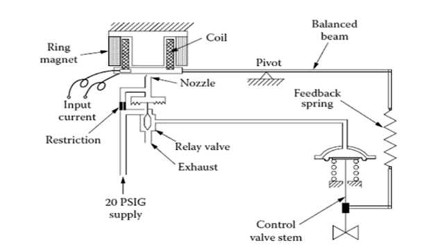
  Control Valves positioner A control valve positioner is a device used to operate the actuator of a control valve to increase and decrease the air load pressure until the valve stem is in equilibrium with the output signal of the process variable instrument controller. Because valve positioners know the exact position of the valve, they provide more precise control than the actuator can achieve on its own. In addition, positioners improve accuracy in the lower part of the valve stroke, where errors are more common. Positioners help control valves respond more quickly to changes in process variables, allowing the system to operate above or below setpoint. Consistent valve position, even with different pressures. Varying pressures on the valves can indicate instability in the control loop. A positioner is a device that helps to stabilize the position of the valve. A positioner allows you to set the distance between the controller and the control valve as well as use a diaphragm or...

Hydraulic Actuators working principle, advantages, disadvantages and applicationa

Image
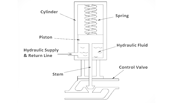
  Hydraulic Actuators Hydraulic Actuators, as used in industrial process control, employ hydraulic pressure to drive an output member. These are used where high speed and large forces are required. The fluid used in hydraulic actuator is highly incompressible so that pressure applied can be transmitted instantaneously to the member attached to it. What is a Hydraulic Actuator ? when a large amount of force is required to operate a valve (for example, the main steam system valves), hydraulic actuators are normally used. Hydraulic actuators come in many designs, piston types are most common. A typical piston-type hydraulic actuator. It consists of a cylinder, piston, spring, hydraulic supply and return line, and stem. The piston slides vertically inside the cylinder and separates the cylinder into two chambers. The upper chamber contains the spring and the lower chamber contains hydraulic oil. The hydraulic supply and return line is connected to the lower chamber and allows hydraulic...