Posts

Showing posts with the label Actuator

What is an Actuator?

What is an Actuator? Basically the actuator follows the sensor feedback and let's say you are controlling the process temperature. For example, room temperature should be maintained using chilled water. In this case, an actuator would be a modulating valve to control the flow of cooling water supply. But, real room temperature feedback will be taken by the sensor. Based on the feedback, the valve will open or close accordingly to maintain the process. Includes actuators such as valves, heaters and drives.
Working Principle of Hydraulic Actuators

Image
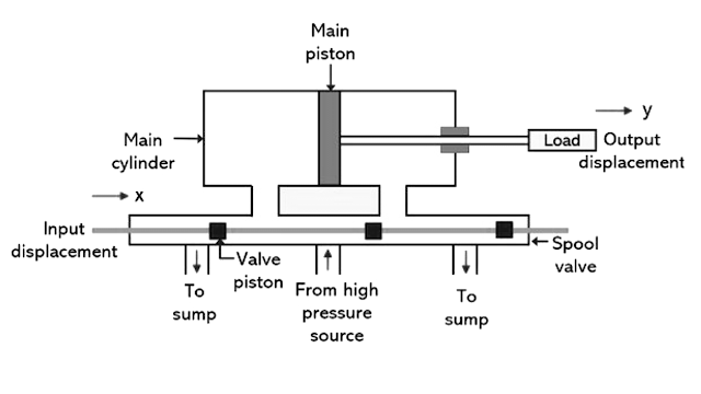
  Working of Hydraulic Actuator The figure below represents the schematic representation of the hydraulic actuator. The major component of the unit is pilot valve also known as spool valve and main cylinder (or power cylinder). It operates in a way that difference in pressure created at the two regions of the main cylinder leads to the occurrence of translational motion of the piston. Let us see the functioning of the hydraulic linear actuator is main cylinder has two regions. These two regions are obtained by dividing the main cylinder with a main piston. Thus, there are two chambers of the main cylinder. The rate with which the fluid flows inside the cylinder is controlled by the spool valve. The spool valve has 4 ports and each port is connected to a different part of the system. Two separate ports are connected to the fluid supply and drain region respectively. While the other two ports are connected separately to the two chambers of the main cylinder. Initially, the spool is prese

Direct and Pilot Actuated

  Direct and Pilot Actuated In the direct-actuated type, the power unit (bellows, diaphragm, and so on) of the thermal actuator is directly connected to the valve plug and develops the force and travel necessary to fully open and close the valve. Direct-actuated regulators are generally simpler, lower in cost, and more truly proportional in action (with somewhat better stability). In the pilot-actuated design, the thermal actuator moves a pilot valve, internal or external. This pilot controls the amount of pressure energy from the control agent (fluid through valve) to a piston or diaphragm, which in turn develops power and thrust to position the main valve plug. The pilot may be internal or external. When external, independently acting multiple pilots are also available. Compared to direct-actuated TCVs, pilot-actuated regulators have smaller bulbs, faster response, and narrower proportional band, and they can handle higher pressures through the valve. Pilot-actuated regulators can al

Hydraulic Actuator System working principle

Image
Hydraulic Actuator System Operating Principle of Hydraulic Actuator System Hydraulic actuator system uses the concept proposed by Pascal generally known as Pascal’s Law or Pascal’s Principle. Pascal’s Law states that the pressure applied at a specific point to a confined fluid in a container is transmitted equally in all the directions within the fluid as well as the walls of the container without any loss. Suppose, if pressure P is applied to an area A, then the resultant force due to an applied pressure will be F = P * A Now, if a certain force F is applied in a smaller area to have pressure P in a confined fluid, then the force produced on a larger area as a result of it can be comparatively larger than the force created by the pressure. In this way, the applied pressure at a certain point is used to generate very large forces and this principle is utilized by various hydraulic systems. Working of Hydraulic Actuator The figure below represents the schematic representation of the hyd

Control Valve Actuator

 Valve Actuator The actuator operates the stem and disk assembly. An actuator may be a manually operated hand wheel, manual lever, motor operator, solenoid operator, pneumatic operator, or hydraulic ram. In some designs, the actuator is supported by the bonnet. In other designs, a yoke mounted to the bonnet supports the actuator. Except for certain hydraulically controlled valves, actuators are outside of the pressure boundary.Yokes, when used, are always outside of the pressure boundary.

Hydraulic Actuators working principle, advantages, disadvantages and applicationa

Image
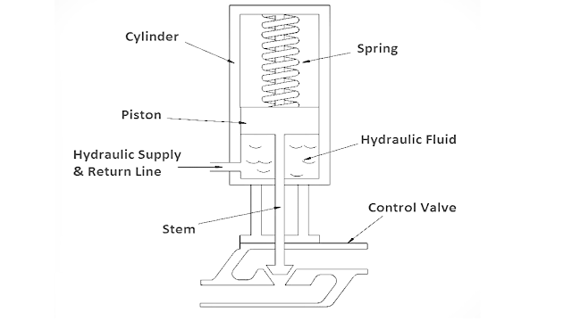
  Hydraulic Actuators Hydraulic Actuators, as used in industrial process control, employ hydraulic pressure to drive an output member. These are used where high speed and large forces are required. The fluid used in hydraulic actuator is highly incompressible so that pressure applied can be transmitted instantaneously to the member attached to it. What is a Hydraulic Actuator ? when a large amount of force is required to operate a valve (for example, the main steam system valves), hydraulic actuators are normally used. Hydraulic actuators come in many designs, piston types are most common. A typical piston-type hydraulic actuator. It consists of a cylinder, piston, spring, hydraulic supply and return line, and stem. The piston slides vertically inside the cylinder and separates the cylinder into two chambers. The upper chamber contains the spring and the lower chamber contains hydraulic oil. The hydraulic supply and return line is connected to the lower chamber and allows hydraulic flu

What Is a Linear Actuator and Most Common Uses for Linear Actuator

  What Is a Linear Actuator? A linear actuator changes the rotational motion of a motor into a straight line. Conventional electric motors move in a circle, while linear actuators move forward and backward. The push and pull action allows the device to slide, tip, and lift items with the push of a button. The design provides operators accurate and precise control over the production. The fluid movement means the linear actuator requires minimal maintenance over its lifespan and comes with natural energy efficiency. They are easier to install than their hydraulic or pneumatic counterparts, cost less, and take up significantly less room. When to Use a Linear Actuator Manufacturers leverage linear actuators in tools and industrial machines, such as printers, sprayers, computers, and valves. Choosing an actuator depends on the product, with hydraulic actuators powering hydraulic car jacks and pneumatic actuators often powering pistons and ignition chambers. Each of these devices offers an

Electric Actuators Introduction, uses, advantages and disadvantages

Image
  Electric Actuators Introduction An electric actuator is a mechanical device used to convert electricity into kinetic energy in either a single linear or rotary motion. It automates damper or valve in order to increase process efficiency and complexity. Designs for electric actuators are based on the specific tasks they accomplish within the processes for which they’re intended, and they can vary in both dimension and size. The motor of an electric actuator can operate on any voltage and is used across many different industries. The most common voltages used in single-phase motors are 115 VAC, 24 VAC, 12 VDC, 24 VDC, 208 VAC and  230 VAC. In addition to these options, three-phase motors also use voltages of 230 VAC and 460 VAC. An actuator’s brake is mounted on top of the motor. It’s responsible for stopping the media from forcing the valve open when it should be closed by locking the motor rotor in position when not in use. The motor start capacitor is the third main component of an

pneumatic actuator types, working advantages and disadvantages

Image
  pneumatic actuator A Pneumatic actuator mainly consists of a piston or a diaphragm which develops the motive power. It keeps the air in the upper portion of the cylinder, allowing air pressure to force the diaphragm or piston to move the valve stem or rotate the valve control element. The valves input is the “control signal.” A simplified diagram of a pneumatic actuator is shown in Figure a. It operates by a combination of force created by air and spring force. The actuator positions a control valve by transmitting its motion through the stem. A rubber diaphragm separates the actuator housing into two air chambers. The upper chamber receives supply air through an opening in the top of the housing. The bottom chamber contains a spring that forces the diaphragm against mechanical stops in the upper chamber. Finally, a local indicator is connected to the stem to indicate the position of the valve. The position of the valve is controlled by varying supply air pressure in the upper chambe

Control Valves actuator and it's types

Image
  Control Valves actuator Introduction Pneumatically operated control valve actuators are the most popular in use. Actuator are also widely used. The pneumatic spring and diaphragm actuator is most commonly specified due to its reliability and simplicity of design. Pneumatically operated piston actuators provide high stem output power for demanding service conditions. The adaptations of the pneumatic and spring piston actuators are available for direct installation on rotary shaft control valves. Electric and electro-hydraulic actuators are more complex and more expensive than pneumatic actuators. They offer advantages where an air supply source is not available, where low ambient temperatures could freeze condensed water in pneumatic supply lines, or where unusually large stem forces are needed. Below is a summary in which the design and characteristics of popular actuator styles are analyzed. An actuator is an assembly fitted to the control valve to provide power for moving the move-