Posts

Showing posts with the label Circuit

What is a Parallel Circuit?

Image
What is a Parallel Circuit? Parallel Circuit  Basically a parallel circuit is one in which the components are directly connected to each other. Each component in a parallel circuit operates at the same voltage as the source. In other words, the voltage across different components in a parallel circuit is the same. [ Vt = V1 = V2 = V3…= Vn ]. And in this circuit two or more paths are available for current flow. The number of current paths is equal to the number of parallel elements. And two or more paths are available for current flow in this circuit. The number of current paths is equal to the number of parallel elements. In a parallel circuit the current is varied and mixed. [ To = I1 + I2 + I3…+In]. In a resistive parallel circuit, the total resistance is less than any of the individual resistances. [ Rt = 1 / (1/R1 + 1/R2+ . . . 1/Rn) ]. In an inductive parallel circuit, the total inductance is less than any individual inductance. [ Lt = 1 / (1/L1 + 1/L2+ . . . 1/Ln)]. and capacitiv

What is a Series Circuit?

Image
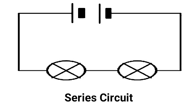
What is a Series Circuit? Series Circuit  Basically this circuit consists of a series of elements connected one after the other. And it is also called one to one connection or cascade connection. A circuit short in series or a break at any point in the circuit causes the entire circuit to become unusable. The total voltage applied to a series circuit is distributed in a series of voltage drops across the various components of the circuit. In other words, the sum of the voltage drops across the individual components in a series circuit equals the total applied voltage. [ Vt = V1 + V2 + V3…+Vn ]. There is only one path available for current flow in this circuit and the current through all the elements in a series circuit is the same. [ It = I1 = I2 =I3 … = In ]. Basically in a resistive series circuit, the total resistance is equal to the sum of the individual resistances. [ Rt =  R1 + R2 + R3…+Rn ]. In an inductive series circuit, the total inductance is equal to the sum of the individu

Circuit Diagram And Its Electrical Component Types

Image
Circuit Diagram And Its Electrical Component Types Circuit Diagram A circuit diagram is an image and essentially shows the interconnection of electrical components in the form of a standardized symbolic representation. A circuit diagram shows actual electrical component connections in image format. And a circuit diagram is known as a graphical representation of a circuit. Circuit A circuit is basically a group of electrical components connected together by wires or soldering. Basically the circuit is designed using soldering is called PCB design. And an electrical circuit is a closed loop of electrical components and uses a battery or power supply to flow electricity in the circuit. Electrical circuit is divided into two types, first is series circuit and second is parallel circuit. 1. Series Circuit Basically a series circuit means that all components carry the same amount of current. And series circuits arrange all components in a line basically in series form. And the disadvantages

Electrical Circuit

Electrical Circuit  An electrical circuit is a group of electrical components such as resistors, capacitors, transistors, diodes and inductors which are connected by wires but now the interconnection of electrical components is done using soldering and is known as PCB design. In an electrical circuit, electrons leave a power source, travel along a conductor, pass through a load to do work, and finally return to the source. It is called a circuit because of the circular path through which electrons flow. In an electrical circuit, electrons travel from the negative side to the positive side.