Types of Compensator
Types of Compensator
Series Compensator
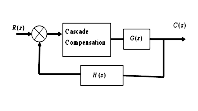
Connecting compensating circuit between error detector and plants known as series or cascade compensation
Feedback Compensator 
Feed forward Compensator

Types of Series Compensator
There are three different types of series compensator
- Lead compensator
- Lag compensator
- Lag-lead compensator
Lead compensator

The lead compensator in a control system produces the output with a phase lead. Here, lead means ahead. It is a type of successor activity.
It consists of a two resistors, named as R1 and R2, and one capacitor C. The transfer function of a system is given by
Transfer function = Output/ Inpute
The output of the lead compensator diagram is an RC circuit, and it depicts that the output is connected across the second branch. It has only one resistor, R2.
So, the output of the circuit is R2.
Vo(s) = R2
Let's find the input.
The input will be the series or parallel combination of the elements (capacitor and resistors). The resistor R1 is connected in parallel with the capacitor C1. The equivalent parallel combination is further connected in series with the resistor R2.
The parallel combination of two elements a and b in a circuit is a x b / a + b
It will be:- R1(1/Cs)/ (R1 + 1/Cs)
The equivalent input is:-
Vi(s) = R2 + R1(1/Cs)/ (R1 + 1/Cs)
Thus, the transfer function of the lag compensator will be
Transfer function = Output/ Input = Vo(s)/Vi(s)
= R2 / {R2 + R1(1/Cs)/ (R1 + 1/Cs)}
= R2(R1Cs + 1)/ {R1R2Cs + 1/(R1 + R2))
Dividing and multiplying the above transfer function with R1 + R2, we get
R2/(R1 + R2) (R1Cs + 1)/{R1R2Cs/(R1 + R2) + 1}
Let, T = R1C
A = R2/ (R1 + R2)
So, the above transfer function can be written as
Vo(s)/Vi(s) = A (Ts + 1)/ (TAs + 1)
We know that the numerator of the transfer function determines the zeroes of the system, and the denominator determines the poles.
Thus, from the given transfer function, we can conclude that
Pole = -1/AT
Zero = - 1/T
The maximum angle that a lead compensator can introduce in the system is given by
Phase angle = sin-1(1 - A / 1 + A)
It can also be written as 90 - 2tan-1(A)1/2
The maximum frequency at the given maximum angle is: 1/T(A)1/2

Location of Lead Compensation pole and zero in s-plane

Effect of Lead Compensation
- The velocity constant Kv increases.
- The slope of the magnitude plot reduces at the gain crossover frequency so that relative stability improves and error decrease due to error is directly proportional to the slope.
- Phase margin increases.
- Response become faster.
Advantages of Lead Compensation
- Due to the presence of phase lead network the speed of the system increases because it shifts gain crossover frequency to a higher value.
- Due to the presence of phase lead compensation maximum overshoot of the system decreases.
- The improved dynamic response of the system leads to a faster response.
- It increases the system's bandwidth.
- It acts as a high pass filter.
Disadvantages of Lead Compensation
- Steady state error is not improved
- It is prone to noise.
- It requires an additional amplifier gain.
Applications of Lead Compensation
- It is used to increase the speed of the transient response. Thus, its applications lie where a fast transient response is required.
Lag compensator

The lag compensator in a control system produces the output with a phase lag. Here, lag means behind or delay.
It consists of a two resistors, named as R1 and R2, and one capacitor C. The transfer function of a system is given by
Transfer function = Output/ Input
The output of the lag compensator diagram is an RC circuit. It clearly depicts that the output is connected across the second branch. It has one resistor R2 and a capacitor C connected in series.
So, the output of the circuit is
Vo(s) = R2 + 1/Cs
Let's find the input.
The input will be the series or parallel combination of the elements (capacitor and resistors). The resistor R1 is connected in series with the series combination of R2 and C. We will first calculate the series combination and further it with the other series combination.
The series combination of two elements a and b in a circuit is a + b
It will be: R2 + 1/Cs
The equivalent input is
Vi(s) = (R1 + R2 + 1/Cs)
Thus, the transfer function of the lag compensator will be
Transfer function = Output/ Input = Vo(s)/Vi(s)
= R2 + 1/Cs/ (R1 + R2 + 1/Cs)
= CsR2 + 1/(Cs(R1 + R2) + 1)
= Ts + 1/ (BTs + 1)
Let, T = CR2
B = (R1 + R2)
So, the above transfer function can be written as
Vo(s)/Vi(s) = 1 + Ts/ 1 + BTs
We know that the numerator of the transfer function determines the zeroes of the system and the denominator determines the poles.
Thus, from the given transfer function, we can conclude that
Pole = -1/BT
Zero = - 1/T
The maximum angle that a lead compensator can introduce in the system is given by:
Phase angle = sin-1(1 - B / 1 + B)
The maximum frequency at the given maximum angle is: 1/T(B)1/2

Location of Lag Compensation pole and zero in s-plane

Effect of Lag Compensation
- Gain crossover frequency increases.
- Bandwidth decreases.
- Phase margin will be increase.
- Response will be slower before due to decreasing bandwidth, the rise time and the settling time become larger.
Advantages of Lag Compensation
- Phase lag network allows low frequencies and high frequencies are attenuated.
- Due to the presence of phase lag compensation the steady state accuracy increases.
- It improves the steady state performance of the system by reducing the steady state error.
- It suppresses the high- frequency noise.
- It acts as low-pass filter, which provides high gain at lower frequencies.
Disadvantages of Lag Compensation
- Due to the presence of phase lag compensation the speed of the system decreases
- It requires a large value of RC (resistor capacitor).
- It decreases the seed of the system's transient response.
Applications of Lag Compensation
- The phase lag reduces the steady state error. Thus, it is used hen the error constants are specified.
Lag-lead compensator

As the name implies, the lag-lead compensator is combination of lag and lead compensator.
The lag compensator in a control system produces the output with a phase lag. The lead compensator in a control system produces the output with a phase lead. Thus, the lag-lead compensator produces the output with phase lg at one frequency region and phase lead at the other frequency region.
It consists of a two resistors, named as R1 and R2, and two capacitors C1 and C2. The transfer function of a system is given by
Transfer function = Output/ Input
The output of the lag compensator diagram is an RC circuit, and it depicts that the output is connected across the second branch. It has one resistor, R2 and a capacitor, C2, connected in series.
So, the output of the circuit is
Vo(s) = R2 + 1/C2s
Let's find the input.
The input will be the series or parallel combination of the elements (capacitor and resistors). The resistor R1 is connected in parallel with the capacitor C1. The second branch has the series combination of the resistor R2 and C2. We will first calculate the series combination of C2 and R2, the parallel combination of R1 and C1, and further both as the series combination.
The series combination of two elements a and b in a circuit is a + b
It will be: R2 + 1/C2s
The parallel combination will be: R1 x 1/C1s/(R1 + 1/C1s)
The equivalent input will now be the series combination of the above listed combinations, which is given by
Vi(s) = R2 + 1/C2s + R1 x 1/C1s/(R1 + 1/C1s)
Vi(s) = {(R2 + 1/C2s) (R1 + 1/C1s) + R1 x 1/C1s}/ ((R1 + 1/C1s)
Thus, the transfer function of the lag compensator will be
Transfer function = Output/ Input = Vo(s)/Vi(s)
=( R2 + 1/C2s)/ {(R2 + 1/C2s) (R1 + 1/C1s) + R1 x 1/C1s}/ ((R1 + 1/C1s)
= (R2 + 1/C2s) (R1 + 1/C1s) /R1R2C1C2s2 + (R1C1 + R2C2 + R1C2)s + 1
Let, AT1 = R1C1
BT2 = R2C2
T1T2 = R1R2C1C2,
if AB = 1
Vo(s)/Vi(s) = (1 + AT1s) (1 + BT2s)/ (1 + T1s) (1 + T2s)
So, the above transfer function can be written as
Vo(s)/Vi(s) = (1 + AT1s) (1 + BT2s)/ (1 + T1s) (1 + T2s)

Advantages of the lag-lead compensator
- Due to the presence of phase lag-lead network the speed of the system increases because it shifts gain crossover frequency to a higher value.
- Due to the presence of phase lag-lead network accuracy is improved.
- We know that the lag compensator improves the steady-state performance of the system, and the lead compensator enhances the speed of the transient response. Thus, the combination of these two (lag-lead compensator) is used when the system's fast response and steady-state performance are required.
Applications of the lag-lead compensator
- It is used in robotics, laser frequency stabilization, satellite control, LCDs (Liquid Crystal Displays), etc.
- It is one of the essential blocks of the analog control systems.
- It is used to improve the system's parameters, such as bandwidth, transient response, and reducing steady state errors.
- It also improves the system's frequency response.
Comments
Post a Comment