Hydraulic Actuators working principle, advantages, disadvantages and applicationa
Hydraulic Actuators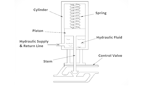

Hydraulic Actuators, as used in industrial process control, employ hydraulic pressure to drive an output member. These are used where high speed and large forces are required. The fluid used in hydraulic actuator is highly incompressible so that pressure applied can be transmitted instantaneously to the member attached to it.
What is a Hydraulic Actuator ?
when a large amount of force is required to operate a valve (for example, the main steam system valves), hydraulic actuators are normally used. Hydraulic actuators come in many designs, piston types are most common. A typical piston-type hydraulic actuator. It consists of a cylinder, piston, spring, hydraulic supply and return line, and stem.
The piston slides vertically inside the cylinder and separates the cylinder into two chambers. The upper chamber contains the spring and the lower chamber contains hydraulic oil. The hydraulic supply and return line is connected to the lower chamber and allows hydraulic fluid to flow to and from the lower chamber of the actuator. The stem transmits the motion of the piston to a valve.
Initially, with no hydraulic fluid pressure, the spring force holds the valve in the closed position. As fluid enters the lower chamber, pressure in the chamber increases. This pressure results in a force on the bottom of the piston opposite to the force caused by the spring. When the hydraulic force is greater than the spring force, the piston begins to move upward, the spring compresses, and the valve begins to open.
As the hydraulic pressure increases, the valve continues to open. Conversely, as hydraulic oil is drained from the cylinder, the hydraulic force becomes less than the spring force, the piston moves downward, and the valve closes. By regulating amount of oil supplied or drained from the actuator, the valve can be positioned between fully open and fully closed.
The principles of operation of a hydraulic actuator are like those of the pneumatic actuator. Each uses some motive force to overcome spring force to move the valve. Also, hydraulic actuators can be designed to fail-open or fail-closed to provide a fail-safe feature.
Operating Principle of Hydraulic Actuator System
Hydraulic actuator system uses the concept proposed by Pascal generally known as Pascal’s Law or Pascal’s Principle.
Pascal’s Law states that the pressure applied at a specific point to a confined fluid in a container is transmitted equally in all the directions within the fluid as well as the walls of the container without any loss.
Suppose, if pressure P is applied to an area A, then the resultant force due to an applied pressure will be
F = P * A
Now, if a certain force F is applied in a smaller area to have pressure P in a confined fluid, then the force produced on a larger area as a result of it can be comparatively larger than the force created by the pressure.
In this way, the applied pressure at a certain point is used to generate very large forces and this principle is utilized by various hydraulic systems.
Working of Hydraulic Actuator
The figure below represents the schematic representation of the hydraulic actuator.

The major component of the unit is pilot valve also known as spool valve and main cylinder (or power cylinder).
It operates in a way that difference in pressure created at the two regions of the main cylinder leads to the occurrence of translational motion of the piston. Let us see the functioning of the hydraulic linear actuator is main cylinder has two regions. These two regions are obtained by dividing the main cylinder with a main piston. Thus, there are two chambers of the main cylinder. The rate with which the fluid flows inside the cylinder is controlled by the spool valve. The spool valve has 4 ports and each port is connected to a different part of the system. Two separate ports are connected to the fluid supply and drain region respectively. While the other two ports are connected separately to the two chambers of the main cylinder. Initially, the spool is present at the neutral position say x = 0 and at this position, there will be no flow of fluid inside the main cylinder. The assembly of the hydraulic actuator is such that the load will move according to the fluid flow. Thus, when input displacement, x is 0 then the output displacement y will also be 0. As soon as a certain input displacement is provided, then the spool moves towards the right. The movement of spool towards the right causes the fluid from the high-pressure source to move towards the left chamber of the main cylinder. Thus, the pressure on the left chamber of the cylinder rises comparatively more than that present on the right chamber. This results in the generation of accelerating force that causes movement of the load. In this way, the direction in which fluid flows corresponds to the direction in which the load moves. This acts as power amplification as discussed in operating principle because the force supplied to displace the valve is comparatively very small than the force generated that actually displaces the load. Hence, in this way hydraulic actuators operate.
Working Principle of Hydraulic Actuators
Hydraulic actuators use liquid pressure rather than instrument air pressure to apply force on the diaphragm to move the valve actuator and then to position valve stem.
Nearly all hydraulic actuator designs use a piston rather than a diaphragm to convert fluid pressure into mechanical force. The high pressure rating of piston actuators lends itself well to typical hydraulic system pressures, and the lubricating nature of hydraulic oil helps to overcome the characteristic friction of piston-type actuators.
Given the high pressure ratings of most hydraulic pistons, it is possible to generate tremendous actuating forces with a hydraulic actuator, even if the piston area is modest.
For example, an hydraulic pressure of 2000 PSI applied to one side of a 3 inch diameter piston will generate a linear thrust exceeding 14000 pounds (7 tons)!
In addition to the ability of hydraulic actuators to easily generate extremely large forces, they also exhibit very stable positioning owing to the non-compressibility of hydraulic oil. Unlike pneumatic actuators, where the actuating fluid (air) is “elastic,” the oil inside a hydraulic actuator cylinder does not yield appreciably under stress. If the passage of oil to and from a hydraulic cylinder is blocked by small valves, the actuator will become firmly “locked” into place.
This is an important feature for certain valve-positioning applications where the actuator must firmly hold the valve position in one position. Some hydraulic actuators contain their own electrically-controlled pumps to provide the fluid power, so the valve is actually controlled by an electric signal. Other hydraulic actuators rely on a separate fluid power system (pump, reservoir, cooler, hand or solenoid valves, etc.) to provide hydraulic pressure on which to operate. Hydraulic pressure supply systems, however, tend to be more limited in physical span than pneumatic distribution systems due to the need for thick-walled tubing (to contain the high oil pressure), the need to purge the system of all gas bubbles, and the problem of maintaining a leak-free distribution network. It is usually not practical to build a hydraulic oil supply and distribution system large enough to cover the entirety of an industrial facility. Another disadvantage of hydraulic systems compared to pneumatic is lack of intrinsic power storage. Compressed air systems, by virtue of air’s compressibility (elasticity), naturally store energy in any pressurized volumes, and so provide a certain degree of “reserve” power in the event that the main compressor shut down. Hydraulic systems do not naturally exhibit this desirable trait.
Advantages of Hydraulic Actuators
Variable hydraulic actuators are widely used as drives of machine tools, rolling mills, pressing and the foundry equipment, road and building machines, transport and agricultural machines,etc. A number of advantages in comparison with mechanical and electric transfers explains such their wide application
- infinitely variable control of gear-ratio in a wide range and an opportunity to create the big reduction ratio
- small specific weight, i.e. the weight of a hydro actuator is in ratio to transmitted capacity(0,2…0,3 kg / kWt)
- opportunity of simple and reliable protection of the engine from overloads
- small sluggishness of the rotating parts, providing fast change of operating modes (start-up, dispersal, a reverser, a stop)
- simplicity of transformation of rotary movement into reciprocating one
- opportunity of positioning a hydraulic engine on removal(distance) from an energy source and freedom in making configuration.
Disadvantages of hydraulic actuators
- efficiency of a volumetric hydraulic actuator is a little bit lower, than efficiency of mechanical and electric transfers, and during regulation it is reduced
- conditions of operation of a hydraulic actuator (temperature) influence its characteristics
- efficiency of a hydraulic actuator is a little reduced in the process of exhaustion of itsresource owing to the increase in backlashes and the increase of outflow of liquid (falling of volumetric efficiency)
- sensitivity to pollution of working liquid and necessity of high culture service.
Applications
- Hydraulic jack
- Hydraulic brake
- Hydraulic ram
- Used as sensor
- Close loop velocity controlling
- Highly precise positioning for heavy loads
Comments
Post a Comment