Posts

Showing posts with the label Flow

Ultrasonic flow meter working principle types and applications

Image
  Ultrasonic flow meter An ultrasonic flow meter can be defined as, a meter that is used to measure liquid velocity with ultrasound to analyze the volume of liquid flow.  Ultrasonic Flow Meters Working Principle Ultrasonic flow meters calculate the flow rate by utilizing the speed of sound through a fluid created by transducers mounted to the pipe wall. There are two types of ultrasonic meters: Doppler and Time-of-Flight. The Doppler ultrasonic meter requires particles in the fluid to reflect sound waves back to the pipe wall transducers. The difference in frequency between the sent and reflected wave is proportional to fluid velocity. The Time-of-Flight ultrasonic meter requires a clean fluid and works by using opposing transducers mounted to transmit/receive sound waves at an angle across the pipe. The difference in the time required to send a pulse along the path between transducers in the direction of flow vs. against the flow is proportional to the fluid velocity. Some models u

Thermal mass flow meter working principle and Applications

Image
  Thermal mass flow meter Thermal mass flow meters are designed to accurately monitor and measure mass flow (as opposed to measuring volumetric flow) of clean gases, a parameter that is not temperature dependent. Therefore, the thermal mass flow meter does not require a correction for changes in gas temperature, pressure, viscosity and density. Thermal Mass Flow meter Working Principle The thermal mass meter measures gas flow based on the concept of convective heat transfer. The flow meters are available in either inline flow bodies or insertion-style. In either case, the meter’s probe inserts into a gas stream of a pipe, stack or duct. Toward the tip of the meter’s probe are two sensors. These sensors are resistance temperature detectors (RTDs) or resistance thermometers and measure temperature. The RTDs consist of durable reference-grade platinum windings clad in a protective 316 SS or Hastelloy C sheath. One of the RTDs is heated by an integrated circuit and functions as the flow se

Orifice flow meter

Image
  Orifice  flow meter An orifice in a pipeline is shown in below figure with a manometer for measuring the drop in pressure (differential) as the fluid passes thru the orifice. The minimum cross sectional area of the jet is known as the “vena contracta.” How does it work? As the fluid approaches the orifice the pressure increases slightly and then drops suddenly as the orifice is passed. It continues to drop until the “vena-contracta” is reached and then gradually increases until at approximately 5 to 8 diameters downstream a maximum pressure point is reached that will be lower than the pressure upstream of the orifice. The decrease in pressure as the fluid passes thru the orifice is a result of the increased velocity of the gas passing thru the reduced area of the orifice. When the velocity decreases as the fluid leaves the orifice the pressure increases and tends to return to its original level. All of the pressure loss is not recovered because of friction and turbulence losses in th

Turbine flow meter

Image
  Turbine flow meter A turbine flow meter is used for volumetric total flow and/or flow rate measurement and has a relatively simple working principle. As fluid flows through the turbine meter, it impinges upon turbine blades that are free to rotate about an axis along the center line of the turbine housing.  Turbine flow meters use the mechanical energy of the liquid to rotate a rotor within the flow stream. The rotational speed is directly proportional to the velocity of the fluid traveling through the meter. These meters are used in multiple industries to reliably measure liquids, gases and vapors. Introduction Turbine flow meters are used to measure clean, dry gases and liquids such as hydrocarbons, chemicals, gases and vapors, fuels and other types of liquids with lower viscosity, and for applications requiring highly accurate and precise measurements. These turbine flow meters are mostly used for military applications. They are also used in blending systems in the petroleum indus

What is a Orifice Plate and explain

Image
  Orifice Plate   The orifice plate is the most common form of restriction that is used in flow measurement. An orifice plate is basically a thin metal plate with a hole bored in the center. It has a tab on one side where the specification of the plate is stamped. The upstream side of the orifice plate usually has a sharp, edge. below Figure shows a representative orifice plate. When an orifice plate is installed in a flow line (usually clamped between a pair of flanges), increase of fluid flow velocity through the reduced area at the orifice develops a differential pressure across the orifice. This pressure is a function of flow rate.  With an orifice plate in the pipe work, static pressure increases slightly upstream of the orifice (due to back pressure effect) and then decreases sharply as the flow passes through the orifice, reaching a minimum at a point called the vena contracta where the velocity of the flow is at a maximum. Beyond this point, static pressure starts to recover as

What is Flange Taps

Image
  Flange Taps   Flange taps are the most widely used pressure tapping location for orifices. They are holes bored through the flanges, located one inch upstream and one inch downstream from the respective faces of the orifice plate. A typical flange tap installation is shown in below Figure. The upstream and downstream sides of the orifice plate are connected to the high pressure and low-pressure sides of a DP transmitter. A pressure transmitter, when installed to measure flow, can be called a flow transmitter. As in the case of level measurement, the static pressure in the pipe-work could be many times higher than the differential pressure created by the orifice plate. In order to use a capsule that is sensitive to low differential pressure, a three valve manifoldhas to be used to protect the DP capsule from being over ranged. The three valve manifold is discussed in more detail in the  level measurement.

What is a Orifice Plate

Image
  Orifice Plate   The orifice plate is the most common form of restriction that is used in flow measurement. An orifice plate is basically a thin metal plate with a hole bored in the center. It has a tab on one side where the specification of the plate is stamped. The upstream side of the orifice plate usually has a sharp, edge. below Figure shows a representative orifice plate. When an orifice plate is installed in a flow line (usually clamped between a pair of flanges), increase of fluid flow velocity through the reduced area at the orifice develops a differential pressure across the orifice. This pressure is a function of flow rate.  With an orifice plate in the pipe work, static pressure increases slightly upstream of the orifice (due to back pressure effect) and then decreases sharply as the flow passes through the orifice, reaching a minimum at a point called the vena contracta where the velocity of the flow is at a maximum. Beyond this point, static pressure starts to recover as

What is a Flow Detectors

Image
  Flow Detectors  To measure the rate of flow by the differential pressure method, some form of restriction is placed in the pipeline to create a pressure drop. Since flow in the pipe must pass through a reduced area, the pressure before the restriction is higher than after or downstream. Such a reduction in pressure will cause an increase in the fluid velocity because the same amount of flow must take place before the restriction as after it. Velocity will vary directly with the flow and as the flow increases a greater pressure differential will occur across the restriction. So by measuring the differential pressure across a restriction, one can measure the rate of flow.

Working Principle of Vortex Flow Meter

Image
  Working Principle of Vortex Flow Meter Vortex flow meters utilize a bluff body or cylinder mounted in a pipe spool that creates alternating vortices behind the cylinder. The frequency of the alternating vortex is proportional to the fluid velocity. Vortex flow meters have no moving parts to maintain or repair, and the signal is read electronically and simply converted to a flow rate. Vortex meters work well with most clean fluids and have similar application ranges to DP  flow  meters. Vortex flow meters are also referred to as vortex shedding flow meters or oscillatory flow meters. These types of flow meters are used to measure the vibrations of the downstream vortexes caused by an obstruction in the flowing stream. Each obstruction has a vital liquid flow speed at which vortex shedding takes place. This vortex shedding occurs at the instant when alternating low pressure zones gets created in the downstream. These sporadic pressure zones enable the barrier to move towards the low pr

Coriolis flow meters working principle advantages, disadvantages and application

Image
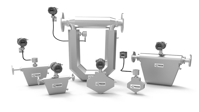
  Coriolis flow meters Coriolis flow meter operate on the principal that, if a particle inside a rotating body moves in a direction toward or away from the center of rotation, the particle generates inertial forces that act on the body.  The operation of a Coriolis flow meter is based on the mechanics of motion. The Coriolis force happens when a mass moves in a rotating inertial frame. The rotation is created by vibrating two opposing tubes on the flow meter. When a fluid flows through the opposed vibrating tubes, the tubes twist due to the Coriolis force. The twisting alternates with the vibration and creates two phase-shifted sinusoidal wave forms on coils mounted to the tubes. The amount of shift is proportional to the mass flow rate. In addition, the frequency of vibration is proportional to the fluid density. Coriolis Flow Meter Principles The basic operation of Coriolis flow meters is based on the principles of motion mechanics. As fluid moves through a vibrating tube it is force