Posts

Showing posts with the label PI

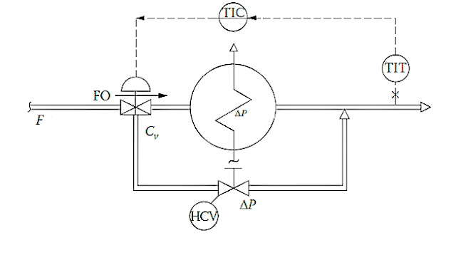
Control strategy for heat exchanger using diverter valve

Image
 Control strategy for heat exchanger using diverter valve 

Feedback control strategy for Condenser Control.

Image
Feedback control strategy for Condenser Control

Three way balancing valve in heat exchanger control

Image
Three way balancing valve in heat exchanger control The role of balancing valves are to control the flow rates in each of the buildings branches to deliver the desired flows in low temperature, chilled, or hot water applications.  At each heat exchanger the balancing valve is set to provide the desired flow rate to maintain comfort and energy. Water velocity noise is not caused by water but by free air, sharp pressure drops, turbulence, or a combination of these, which in turn cause cavitation or flashing of water into steam.”  When using three-way control valves, it is recommended that a manual balancing valve be installed in the exchanger bypass. The opening of this valve should be so adjusted that its pressure drop equals that of the exchanger at normal load. The resistance to flow in such installations will be maximum when one of the paths is closed and the other is fully open, whereas minimum resistance will be experienced when the valve divides the flow equally between the two pa

Cascade control strategy for output temperature control of heat exchanger

Image
Cascade control strategy for output temperature control of heat exchanger

Degrees of freedom for Reboiler

Degrees of freedom for  Reboiler Degrees of freedom The degrees of freedom of a process define the maximum number of independently acting automatic controllers that can be placed on a process  Degrees of freedom = number of variables – number of equations Reboiler In this case there are only two process variables and one defining equation is  [HsWs =H1W1] Two process variables are two flow variables  hence the number of degrees of freedom of that process is one.  Thus, a only one automatic controllers can be placed on it.

Degrees of freedom for Liquid to liquid heat exchanger

Degrees of freedom for Liquid to liquid heat exchanger Degrees of freedom The degrees of freedom of a process define the maximum number of independently acting automatic controllers that can be placed on a process  Degrees of freedom = number of variables – number of equations Liquid to liquid heat exchanger In this case there are six process variables and one defining equation is  [ CpF(Th1-Th2) = CpcFc(T2c-T1c)] Six process variables are four temperature and and two flow variable  hence the number of degrees of freedom of that process is five.  Thus, a maximum of five automatic controllers can be placed on it.

Degrees of freedom for Steam heater

Degrees of freedom for Steam heater Degrees of freedom The degrees of freedom of a process define the maximum number of independently acting automatic controllers that can be placed on a process  Degrees of freedom = number of variables – number of equations Steam heater In this case there are four process variables and one defining equation is  [ HsWs= CpW(T2-T1)] Four process variables are two flow and two temperatures hence the number of degrees of freedom of that process is three.  Thus, a maximum of three automatic controllers can be placed on it.

Cascade control strategy for steam heater

Image
 Cascade control strategy for steam heater

Piping and Instrumentation Diagram (P&ID)

Piping and Instrumentation Diagram (P&ID) Piping and instrumentation diagrams (P&IDs) lie somewhere in the middle between process flow diagram and loop diagrams. Piping and instrumentation shows the layout of all relevent process vessels, pipes, and machinery, but with instruments superimposed on the diagram showing what gets measured and what gets controlled. Here, one can view the flow of the process as well as the information between instruments measuring and controlling the process.
process variables, classify input and output variables, determine control objectives and appropriate manipulated variables for Evaporators Process Variables Level of Solution, Temperature of Solution, Concentration Density. Input Variables Dilute feed Solution, Steam Flow. Output Variables Vapor, Steam, Product. Control Objectives The main objective of evaporators is to get a concentrated product by vaporizing volatile liquid, Out evaporation process, Evaporation is conducted by non volatile solids and volatile solvent to produce this liquid. Manipulated Variables Flow Rate of the feed solution, Discrete signal of the outlet value control.

process variables, classify input and output variables, determine control objectives and appropriate manipulated variables for Evaporators

process variables, classify input and output variables, determine control objectives and appropriate manipulated variables for Evaporators Process Variables Level of Solution, Temperature of Solution, Concentration Density. Input Variables Dilute feed Solution, Steam Flow. Output Variables Vapor, Steam, Product. Control Objectives The main objective of evaporators is to get a concentrated product by vaporizing volatile liquid, Out evaporation process, Evaporation is conducted by non volatile solids and volatile solvent to produce this liquid. Manipulated Variables Flow Rate of the feed solution, Discrete signal of the outlet value control.

process variables, classify input and output variables, determine control objectives and appropriate manipulated variables for Dryers

process variables, classify input and output variables, determine control objectives and appropriate manipulated variables for Dryers Process Variables  Temperature, Drying Period, Surrounding Temperature. Input Variables  Feed Flow, Input Temperature of Dry Air, Input Moisture of Solid and Feed Flow . Output Variables  Dred Product Moisture Content, Exhoust Air Temperature, The Temperature of Air Product  mixture (for spray dryers), Exhaust air Humidity, Product Quality (S, flavour, textures, activity, etc.); these properties are generally difficult (or impossible) to measure online and the cost is often too high. Control Objectives maintenance of Dried Product Quality, Maxima of throughout of optimal, Energy efficiency and minimum cost, Stability of process. Manipulated Variables Heating rate (e.g., inlet air or steam temperature), Solids feed rate (e.g., screw conveyor speed, discharge rate), Airflow rate (for direct dryers), Rotational speed (for rotary dryers)

Recipe Management System

Recipe Management System  A recipe management system is a software application that manages the complex relationships and processes related to a company’s production recipes. They store the recipes, enable recipe modification, generate data required for production records, and even provide the ability to launch tasks and processes. Recipe management systems are most effective when integrated with a manufacturing execution system (MES) or other higher-level control systems. Recipe management can also be a module within an MES. In manufacturing, a recipe is a set of instructions or steps needed to operate a machine, combine ingredients or raw materials in a certain way and in certain ratios, or otherwise process the materials to achieve the desired end product. Common Features of a Recipe Management System Recipe versioning. Recipe archiving. Allocation of equipment. Automation of recipe procedures. Product variant control between similar products. Generation of material flow, execution

Batch Process Management

Batch Process Management Batch process management involves various activities like process control, unit supervision, process management, production planning and scheduling, production management, management of production information, and recipe management.  A batch management system based on ISA S88 allows the physical model to be created based on the P&I diagrams and a database of all materials. Batch Management System is a separate system at the supervisory level in the control system hierarchy. It uses an open database like SQL Server for storing the materials data and the recipe information. Although the S88 standard was available since 1995, it was not very popular since the Batch Management Systems based on it were far too expensive and its implementation required a lot of customization, which in turn required highly skilled engineers for implementation and support. The automation systems in those days were also not so open and flexible, which made adapting to such Batch Man

Characteristics of Dryer

Characteristics of Dryer The requirements and characteristics of any industrial dryer control system are 4 Accuracy Stability Speed of response Robustness Accuracy:  The exit product moisture content must be close to the desired value. Stability:  The system must not oscillate; otherwise, large fluctuations in output moisture content would occur. Speed of response:  Any disturbances (e.g., changes in input moisture content) should be quickly offset by the controller in order to provide acceptable upset recovery time and system stability. Robustness:  The control system should be able to operate successfully over a wide range of process conditions.

Objectives of Dryers

Objectives of Dryers   The basic objectives of a dryer control system are  Maintenance Maximization Avoidance  Reduction  Suppression  Stable  Optimization Maintenance : Maintenance of desired dried product quality, irrespective of disturbances in the drying operation and variations in feed supply Maximization : Maximization of throughput at optimal energy efficiency and minimum cost. Avoidance : Avoidance of over drying and under drying; under drying may result in spoilage, in the case of grains and foodstuffs, whereas over drying of the product results in increased energy costs and reduced yields as the price of some products is based on a specific moisture content; it may also cause thermal damage to heat-sensitive products  Reduction : Reduction of fire hazard, defective product, and particle emission Suppression : Suppression of the influence of external disturbances Stable : Stable drying process Optimization : Optimization of the performance of the drying process

Cascade control strategy used for control of temperature in an exothermic chemical reactor

Image
Cascade control strategy used for control of temperature in an exothermic chemical reactor

Steam Pressure Control in Boiler

Steam Pressure Control in Boiler Steam pressure is the key variable that indicates the state of balance between the supply and demand for steam. If supply exceeds demand, the pressure will rise. Conversely, if demand exceeds supply, the pressure will fall. Plants may experience fluctuations in demand due to batch processes or other process changes. In this case, a steam flow feedforward signal is used with steam pressure control. The term Plant Master is most applicable to the situation in which more than one boiler supplies a common steam header. In this case, there are multiple boiler masters but only one plant master. The plant master generates the master firing rate demand signal that drives the individual boilers in parallel. With multiple boilers, the Plant Master is typically configured with a variable gain, based on the number of boilers in automatic mode. 

Shrink and Swell effect in boiler

Shrink and Swell effect in boiler Shrink  effect  Now as the steam pressure starts increasing steadily the boiler pressure increases and boiling point of water also starts increasing which lead to decrease in bubble formation and level starts dropping and water level seems decreasing. Now automatic water level control valve opens and cool water enters the system and bubbles burst leading to decrease in level of water more. This effect is called shrinkage. Swell effect  Let us suppose discharging of cargo in a tanker is going on. Now due to sudden increase in steam demand due to starting of another copt or due to sudden increase in rpm of copt’s there is a sudden drop in boiler pressure. This sudden drop in pressure leads to vapourization of water as boiling point of water decreases with decrease in pressure. Hence the formation of bubbles inside the boiler makes the level of water looks like increased which in real in not there. This phenomenon is known as swelling which leads to closu

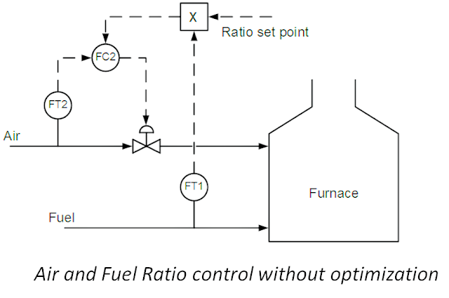
Air and Fuel Ratio Control

Image
Air and Fuel Ratio Control In Combustion processes, air/fuel ratio is normally expressed on a mass basis. We get maximum useful heat energy if we provide air to the combustion zone at a mass flow rate (e.g. ib/min, kg/hr) that is properly matched to the mass flow rate of fuel to the burner. Air and fuel ratio control Consider this generic equation for fuel combustion chemistry: Fuel + Air =Useful heat + CO2 + H2O + CO + Unburned Fuel + Waste Heat Up the Stack ( CO + Unburned Fuel ) Increases as combustion air Decreases  ( Waste Heat Up the Stack ) Increases as combustion air Increases  Where CO2 = Carbon dioxide  CO = Carbon monoxide  H2O = Water  Air = 21% oxygen (O2) and 79% nitrogen (N2)  Fuel = Hydrocarbon such as natural gas or liquid fuel oil  Normally Air/Fuel ratio control is known as series control This means the change in air flow rate occurs as per ratio set only after the change has occurred in fuel flow rate. But in boilers used in power plants, fuel and air should be cont