Metal detector, Water Flow & Heartbeat Sensor
Metal detector, Water Flow & Heartbeat Sensor
Metal detector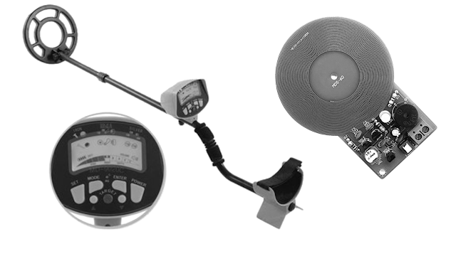

Introduction
Metal detector is a device that can detect metal, the basics can make a sound when it is near some metal.
Metal detectors work on the principle of transmitting a magnetic field and analysing a return signal from the target and environment.
when some metals are coming close to the coil the amplitude of the reflective pulse is getting little lower and a duration of the pulse a little longer.
The need for detection is very clear to protect our self from any kind of danger.
Principle of operation
The operation of a metal detector is based on the principle of electromagnetic induction.
Metal detectors contain one or more inductor coils. When metal is placed in a close proximity to a varying magnetic field (generated by the coil or coils), currents are induced in the metallic part.
These current are called eddy Currents. The eddy Currents, in turn, induce their own magnetic field ( called eddy field).
These fields act in such a direction as to oppose that generated by the coils. The resultant field and using a specially designed electronic circuit can indicate the type of material being magnetized.
Here in our metal detector circuit transistor is used as a colpitts oscillator.
If we increase L1’s inductance it will cause the decrease in frequency and if we decrease this L1’s inductance it will cause the increase in frequency.
Types of Metal detectors
- Beat-frequency oscillator (BFO)
- Pulse induction detector (PI),
- Very Low Frequency (VLF).
How Do Metal Detectors Work?
Metal detectors work by transmitting an electromagnetic field from the search coil into the ground. Any metal objects (targets) within the electromagnetic field will become energised and retransmit an electromagnetic field of their own. The detector’s search coil receives the retransmitted field and alerts the user by producing a target response. Minelab metal detectors are capable of discriminating between different target types and can be set to ignore unwanted targets.
1. Control Box
The control box contains the detector’s electronics. This is where the transmit signal is generated and the receive signal is processed and converted into a target response.
2. Search Coil
The detector’s search coil transmits the electromagnetic field into the ground and receives the return electromagnetic field from a target.
3. Transmit Electromagnetic Field (visual representation only - blue)
The transmit electromagnetic field energises targets to enable them to be detected.
4. Target
A target is any metal object that can be detected by a metal detector. In this example, the detected target is treasure, which is a good (accepted) target.
5. Unwanted Target
Unwanted targets are generally ferrous (attracted to a magnet), such as nails, but can also be non-ferrous, such as bottle tops. If the metal detector is set to reject unwanted targets then a target response will not be produced for those targets.
6. Receive Electromagnetic Field (visual representation only - yellow)
The receive electromagnetic field is generated from energised targets and is received by the search coil.
7. Target Response (visual representation only - green)
When a good (accepted) target is detected the metal detector will produce an audible response, such as a beep or change in tone. Many Minelab detectors also provide a visual display of target information such as an ID number or 2 dimensional display.
Key detecting concepts
Frequency
The frequency of a metal detector is one of the main characteristics that determines how well targets can be detected. Generally, a single frequency detector that transmits at a high frequency will be more sensitive to small targets and a single frequency detector that transmits at low frequencies will give more depth on large targets. Minelab’s single frequency technologies are VLF and VFLEX.
Minelab’s world-leading BBS, FBS, MPS and new revolutionary Multi-IQ technologies transmit multiple frequencies simultaneously and are therefore sensitive to small and deep large targets at the same time.
Ground Balance
Ground Balance is a variable setting that increases detection depth in mineralised ground. This ground may contain salts, such as in wet beach sand or fine iron particles, such as in red earth. These minerals respond to a detector’s transmit field in a similar way that a target does. Due to the much larger mass of the ground compared to a buried target, the effect of mineralisation can easily mask small targets. To correct this the Ground Balance setting removes the responding ground signals, so you clearly hear target signals and are not distracted by ground noise.
There are three main types of Ground Balance:
Manual Ground Balance
Manually adjust the Ground Balance setting, so the minimum amount of ground signal is heard.
Automatic Ground Balance
The detector automatically determines the best Ground Balance setting. This is quick, simple and more accurate than a manually set Ground Balance.
Tracking Ground Balance
The detector continuously adjusts the Ground Balance setting while detecting. This ensures that the Ground Balance setting is always correct.
Minelab detectors use exclusive advanced technologies for superior ground balancing capabilities that cannot be matched by any other detectors.
Discrimination
Discrimination is a metal detector’s ability to identify buried targets based on their conductive and/or ferrous properties. By accurately identifying a buried target you can decide to dig it up or consider it as junk and continue searching. Minelab detectors produce target identification (Target ID) numbers and/or Target Tones to indicate the type of target that has been detected.
There are four main types of discrimination in Minelab detectors:
Variable discrimination
The simplest type of discrimination which uses a control knob to adjust the level of discrimination.
Iron Mask/Iron Reject
Used mostly with gold prospecting detectors to ignore iron junk.
Notch discrimination
Allows specific target types to be accepted or rejected.
Smartfind
The most advanced form of discrimination. Target IDs are plotted based on both ferrous and conductive properties on a two dimensional (2D) display. Individual segments or larger areas of the display can be shaded to reject unwanted targets.
Detection depth factors
The most common question about metal detectors is ‘How deep do they go?’
The simple answer is "as deep as the diameter of the coil". So detectors with larger coils will detect deeper.
Target Size
Large targets can be detected deeper than small targets.
Target Shape
Circular shapes like coins and rings can be detected deeper than long thin shapes like nails.
Target Orientation
A horizontal coin (e.g. lying flat) can be detected deeper than a vertical coin (e.g. on edge).
Target Material
High conductive metals (e.g. silver) can be detected deeper than low conductive metals (e.g. lead or gold).
Applications
- Airport and Building Security
- Construction Industry
- Civil Engineering
- Land Mine Detection
Water Flow

Water flow sensors are installed at the water source or pipes to measure the rate of flow of water and calculate the amount of water flowed through the pipe. Rate of flow of water is measured as liters per hour or cubic meters.
Water flow sensor consists of a copper body, a water rotor, and a hall-effect sensor. When water flows through the rotor, rotor rolls, its speed changes with different rate of flow.
Introduction
Flow is defined as the quantity of fluid (gas, liquid, vapour or sublimate) that passes a point per unit timeIt can be presented by a simple equation: Flow (Q) = quantity/time
It is the rate of change of a quantity. It is either volumetric or mass flow rate.
Properties Affecting Fluid Flow
Velocity of Fluid – the fluid speed in the direction of flow. The fluid velocity depends on the head pressure that is forcing the fluid through the pipe. The greater head pressure, the faster fluid will flow.Pipe size – the larger the pipe, the greater the potential flow rate
Pipe friction – reduces the flow rate through the pipe. Flow rate of the fluid is slower near walls of the pipe that at the center.
Fluid viscosity – its physical resistance to flow.
The specific gravity of fluid – at any given operating condition, the higher fluid’s specific gravity, the lower its flow rate.
Fluid condition – the condition of fluid (clear or dirty) is one of the limitations in flow measurement, some measuring devices blocked/plugged or eroded if dirty fluids are used.
Velocity Profiles – it has major effect on the accuracy of most flow meters. It can be laminar, transitional or turbulent flow. Properties Affecting Fluid Flow
Importance of Fluid Measurement
Measuring flow is one of the most important aspects of process controlThe most diverse substances are transported and distributed in piping system
The fluid flowing through pipes have different properties, so different flow measuring devices are used
The maintenance of definite rates of flow is important for maximum efficiency and production
What is Water Flow Sensor?
Huge industrial plants, commercial and residential buildings require a large amount of water supply. The public water supply system is used to meet this requirement. To monitor the amount of water being supplied and used, the rate of flow of water has to be measured. Water flow sensors are used for this purpose.Water flow sensors are installed at the water source or pipes to measure the rate of flow of water and calculate the amount of water flowed through the pipe.
Differential pressure flow meters
- Coriolis Flow meter
- Vortex Flow meter
- Ultrasonic Flow meter
- Electromagnetic Flow meter
- Thermal Flow meter
Working Principle
Water flow sensor consists of a plastic valve from which water can pass. A water rotor along with a hall effect sensor is present the sense and measure the water flow.When water flows through the valve it rotates the rotor. By this, the change can be observed in the speed of the motor. This change is calculated as output as a pulse signal by the hall effect sensor. Thus, the rate of flow of water can be measured.
The main working principle behind the working of this sensor is the Hall effect. According to this principle, in this sensor, a voltage difference is induced in the conductor due to the rotation of the rotor. This induced voltage difference is transverse to the electric current.
When the moving fan is rotated due to the flow of water, it rotates the rotor which induces the voltage. This induced voltage is measured by the hall effect sensor and displayed on the LCD display.
The water flow sensor can be used with hot waters, cold waters, warm waters, clean water, and dirty water also. These sensors are available in different diameters, with different flow rate ranges.
These sensors can be easily interfaced with microcontrollers like Arduino. For this, an Arduino microcontroller board for processing, a Hall effect water flow sensor, a 16×2 LCD display, and Breadboard connecting wires are required. The sensor is placed at the water source inlet or at the opening of the pipe.
The sensor contains three wires. Red wire to connect with supply voltage. Black wire to connect to ground and a yellow wire to collect output from Hall effect sensor. For supply voltage 5V to 18V of DC is required.
Feature
Compact, Easy to Install
High Sealing Performance
High Quality Hall Effect Sensor
RoHS Compliant
Applications of Water Flow Sensor
- Water flow sensors can measure the rate of flow of water either by measuring velocity or displacement. These sensors can also measure the flow of water like fluids such as measuring milk in a dairy industry etc…
- There are various types of water flow sensors available based on their diameter and method of measuring. A cost-effective and most commonly used water flow sensor is Paddlewheel sensor. It can be used with water-like fluids.
- For the type of applications where a straight pipe is not available for inlet, Positive displacement flow meter is used. This type of water flow sensor can be used for viscous liquids also.
- For working with dirty water and wastewater which may be conductive, Magnetic flow meter is used. For applications such as sewage water, slurries, and other dirty liquids Ultrasonic flow meters are used.
- The LCD display is used to display the measurements. The magnetic hall effect water flow sensor outputs a pulse of every revolution of the rotor. The hall effect sensor present in the device is sealed from water to keep it safe and dry.
Example of Water Flow Sensor
YFS201 Hall effect sensor is an example of this sensor. These sensors also require a display to display the measurements. This sensor outputs 4-5 pulses for every liter of liquid flowing through it per minute. It has a working flow rate of 1-30liters per minute. Easy to use and cost-effectiveness are the important characteristics of this sensor. Heart beat Sensor

Heart beat sensor is designed to give
digital output of heat beat when a finger is
placed on it. When the heart beat detector
is working, the beat LED flashes in unison
with each heart beat. This digital output
can be connected to microcontroller
directly to measure the Beats Per Minute
(BPM) rate. It works on the principle of
light modulation by blood flow through
finger at each pulse.
Features
• Heat beat indication by LED
• Instant output digital signal for directly connecting to microcontroller
• Compact Size
• Working Voltage +5V DC
Specification
Parameter and Value
- Operating Voltage - +5V DC regulated
- Operating Current - 100 mA
- Output Data Level - 5V TTL level
- Heart Beat detection - Indicated by LED and Output High Pulse
- Light source - 660nm Super Red LED
Pin Details
Board has 3-pin connector for using the sensor. Details are marked on PCB as below.
- +5V - Power supply Positive input
- OUT - Active High output
- GND - Power supply Ground
Working

The sensor consists of a super bright red LED and light detector. The LED needs to be super bright as the maximum light must pass spread in finger and detected by detector. Now, when the heart pumps a pulse of blood through the blood vessels, the finger becomes slightly more opaque
and so less light reached the detector. With each heart pulse the detector signal varies. This variation is converted to electrical pulse. This signal is amplified and triggered through an amplifier which outputs +5V logic level signal. The output signal is also indicated by a LED which blinks on each heart beat.
Using the Sensor
• Connect regulated DC power supply of 5 Volts. Black wire is Ground, Next middle wire is
Brown which is output and Red wire is positive supply. These wires are also marked on PCB.
• To test sensor you only need power the sensor by connect two wires +5V and GND. You can leave the output wire as it is. When Beat LED is off the output is at 0V.
• Put finger on the marked position, and you can view the beat LED blinking on each heart beat.
• The output is active high for each beat and can be given directly to microcontroller for interfacing applications.

Applications
• Digital Heart Rate monitor
• Patient Monitoring System
• Bio-Feedback control of robotics and applications
Sample Application: Digital Heart Beat Monitor
Let’s use this heart beat sensor and build a digital heart beat monitor. When a finger is put in the sensor, it displays the beats per minute (BPM) rate.

monitored by the program whenever this input goes high. Internally to U2, there is a counter which counts how many 1ms intervals there are between two high going heart beat pulses. This number is then divided by 60,000 and the result is the pulse rate. For example, if the pulse rate is 60 BPM (beats per minute) there will be a pulse every second. The duration of one heart beat will be one seconds or 1000 x 1ms. Dividing 60,000 by 1000 will give the correct result of 60 which is shown on the display. If there is invalid result (BPM>200) it is invalid and waits for next cycle.
Comments
Post a Comment