Positive displacement flow meter working principle and applications
Positive displacement flow meter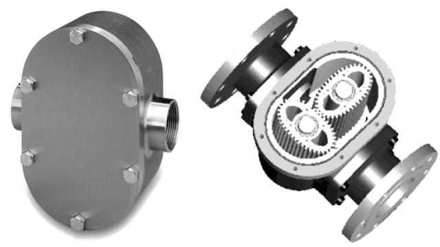

Introduction
A positive displacement meter is a type of flow meter that requires fluid to mechanically displace components in the meter in order for flow measurement. Positive displacement flow meters measure the volumetric flow rate of a moving fluid or gas by dividing the media into fixed, metered volumes.
Positive displacement flow meters are very accurate and have high turndown. They can be used in very viscous, dirty and corrosive fluids and essentially require no straight runs of pipe for fluid flow stream conditioning though pressure drop can be an issue. They are widely used in the custody transfer of oils and liquid fluids (gasoline) and are applied on residential home natural gas and water metering.
A diaphragm meter, with which most homes are equipped, is an example of a positive displacement meter. This type of meter is appealing in certain custody transfer flow applications where it is critical that the metering be functional in order for any flow to take place.
PD flow meters, with internal wiping seals, produce the highest differential pressure (and subsequently greatest pressure drop head loss) of all the flow meter types. Meters that rely on a liquid seal create a relatively low pressure drop.
Positive-displacement (PD) meters can measure both liquids and gases. Like turbine meters, PD flow meters work best with clean, non-corrosive, and non-erosive liquids and gases, although some models will tolerate some impurities.
Because of their high accuracy, PD meters are widely used at residences to measure the amount of gas or water used. Other applications include: chemical injection, fuel measurement, precision test stands, high pressure, hydraulic testing, and similar precision applications.
Some designs require that only lubricating fluid be measured, because the rotors are exposed to the fluid. PD meters differ from turbine meters in that they handle medium and high-viscosity liquids well. For this reason, they are often used to measure the flow of hydraulic fluids.
Compared with orifice-type meters, PD meters require very little straight upstream piping since they are not sensitive to uneven flow distribution across the area of the pipe. Positive displacement flow meters can provide better relative accuracy at low flows than orifice-type flow meters.
However, a positive displacement meter can be considerably heavier and more costly than non-positive-displacement types such as orifice plates, magnetic or vortex flow meters.
What is a Positive displacement flow meter ?
Positive Displacement (PD) Flow meters are volumetric flow measurement instruments that measure flow by passing a precise volume of fluid with each revolution. Positive Displacement flow meters are precision instruments whose internal moving components are hydraulically locked in tandem with the volume of fluid moving through the flow meter.
The result is that the meter can measure intermittent flows, very low flow rates, and liquids of almost any viscosity. The Positive Displacement meter instantly moves when there is fluid motion, and instantly stops when the fluid motion stops.
This type of measurement is not affected by the liquid’s viscosity, density or the turbulence in the pipe. All incompressible fluids will occupy the same volume and there is no need to correct the meter’s output to compensate for these factors.
Positive Displacement Meter is a type of flow meter that requires fluid to mechanically displace components in the meter in order for flow measurement. Positive displacement (PD) flow meters measure the volumetric flow rate of a moving fluid or gas by dividing the media into fixed, metered volumes (finite increments or volumes of the fluid).
A basic analogy would be holding a bucket below a tap, filling it to a set level, then quickly replacing it with another bucket and timing the rate at which the buckets are filled (or the total number of buckets for the “totalized” flow). With appropriate pressure and temperature compensation, the mass flow rate can be accurately determined.
These devices consist of a chamber(s) that obstructs the media flow and a rotating or reciprocating mechanism that allows the passage of fixed-volume amounts. The number of parcels that pass through the chamber determines the media volume.
The rate of revolution or reciprocation determines the flow rate. There are two basic types of positive displacement flow meters. Sensor-only systems or transducers are switch-like devices that provide electronic outputs for processors, controllers, or data acquisition systems.
Types of Positive Displacement Flow Meters
- Reciprocating or oscillating piston
- Gear
- Oval Gear
- Helical Gear
- Nutating disk
- Rotary vane
- Diaphragm
Reciprocating or oscillating piston
Each piston is mechanically or magnetically operated to fill a cylinder with the fluid and then discharge the fluid. Each stroke represents a finite measurement of the fluid.
Gear
Gear flow meters rely on internal gears rotating as fluid passes through them. There are various types of gear meters named mostly for the shape of the internal components
Oval Gear
Two rotating oval gears with synchronized teeth “squeeze” a finite amount of fluid through the meter for each revolution. With oval gear flow meters, two oval gears or rotors are mounted inside a cylinder.
As the fluid flows through the cylinder, the pressure of the fluid causes the rotors to rotate. As flow rate increases, so does the rotational speed of the rotors.
Helical Gear
Helical gear flow meters get their name from the shape of their gears or rotors. These rotors resemble the shape of a helix, which is a spiral-shaped structure.
As the fluid flows through the meter, it enters the compartments in the rotors, causing the rotors to rotate. Flow rate is calculated from the speed of rotation.
Nutating disk
A disk mounted on a sphere is “wobbled” about an axis by the fluid flow and each rotation represents a finite amount of fluid transferred. A nutating disc flow meter has a round disc mounted on a spindle in a cylindrical chamber.
By tracking the movements of the spindle, the flow meter determines the number of times the chamber traps and empties fluid. This information is used to determine flow rate.
Rotary vane
A rotating impeller containing two or more vanes divides the spaces between the vanes into discrete volumes and each rotation (or vane passing) is counted.
Diaphragm
Fluid is drawn into the inlet side of an oscillating diaphragm and then dispelled to the outlet. The diaphragm oscillating cycles are counted to determine the flow rate.
Positive Displacement Flow meter working principle
Positive Displacement flow meters are the only flow measuring technology to directly measure the volume of fluid that passes though the flow meter. It achieves this by trapping pockets of fluid between rotating components housed within a high precision chamber. This can be compared to repeatedly filling a beaker with fluid and pouring the contents downstream while counting the number of times the beaker is filled.
Rotor rotational velocity is directly proportional to flow rate, since the flow of fluid is causing the rotation. electronic flow meters the rotating components contain magnets that activate various sensor options located outside the fluid chamber. Mechanical positive displacement flow sensors rely on the rotation to drive either a magnetic coupling or a direct gear train connected to the mechanical counter.
PD flow meters do not require a power supply for their operation and do not require straight upstream and downstream pipe runs for their installation. Positive displacement flow meters are available in sizes from in to 12 in and can operate with turn downs as high as 100:1, although ranges of 15:1 or lower are much more common. Slippage between the flow meter components is reduced and metering accuracy is therefore increased as the viscosity of the process fluid increases.

The process fluid must be clean. Particles greater than 100 microns in size must be removed by filtering. Positive displacement meters operate with small clearances between their precision-machined parts; wear rapidly destroys their accuracy. For this reason, PD meters are generally not recommended for measuring slurries or abrasive fluids. In clean fluid services, however, their precision and wide rangeability make them ideal for custody transfer and batch charging. They are most widely used as household water meters. Millions of such units are produced annually. In industrial and petrochemical applications, Positive displacement flow sensors are commonly used for batch charging of both liquids and gases.
Although slippage through the positive displacement flow meter decreases (that is, accuracy increases) as fluid viscosity increases, pressure drop through the meter also rises. Consequently, the maximum (and minimum) flow capacity of the flow meter is decreased as viscosity increases. The higher the viscosity, the less slippage and the lower the measurable flow rate becomes. As viscosity decreases, the low flow

Positive Displacement (PD) Meters Explained Briefly
PD flow meters are mainly named after the inbuilt mechanical device in the meter unit. Various types of positive displacement flow meters are available for industrial use. All these types are based on the common operating principle. Besides, they all are volumetric flow measuring devices.
Major types of positive displacement flow meters are mentioned below
Reciprocating Piston Meters
These are also known as oscillating piston flow meters. These are one of the oldest positive displacement type flow meter designs. These types of meters are mainly of single or multiple-piston types.
Other types available are double acting pistons and rotary pistons. Selection of a particular type of piston meter depends on the range of flow rates necessary for an application.
Although piston meters are smaller in size and considered apt for handling only low flows of viscous liquids, yet they are proficient enough to deal with an extensive range of liquids. Major application areas of a reciprocating piston meter include viscous fluid services like oil metering on engine test stands, specifically where turndown ratio is not considered much crucial.
Also these meters can be employed on residential water service where they tend to pass partial quantities of dirt and fine sand along with water.

Oval-gear Meters
These types of meters consist of two rotating, oval-shaped gears constructed with synchronized, close fitting teeth. In an oval gear meter, the rotation of gear shafts causes a fixed amount of liquid to pass through the meter. By monitoring the number of shaft rotations, one can calculate liquid flow rate.
These types of meters prove to be very accurate when slippage between the housing and the gears is set very small. Turndown ratio of an oval gear meter gets influenced by the lubricating properties of the process fluid.

Nutating disk Meters
These are the widely used positive displacement type flow meters. They consist of a movable disk which is positioned on a concentric sphere situated inside a spherical side-walled unit. Universally, they are employed as residential water meters.
They exist in various sizes and capacities and can be constructed from a wide range of materials. Their typical size range varies from 5/8-in to 2-in sizes. They are ideal for pressure ranges around 150-psig with an upper limit of 300 psig.

Rotary vane Meters
These types of meters exist in different designs. However, they all work on the same operating principle. These meters basically include uniformly divided rotating impellers with two or more compartments inside the chamber. The number of rotations of the impeller are counted and recorded in volumetric units. These types of meters are frequently employed in the petroleum industry.
Based upon the construction material, maximum pressure and maximum temperature limits of rotary vane meters are 350°F and 1,000 psig respectively. Their Viscosity limit ranges between 1 and 25,000 centipoise.

Helix Meters
These types of meters are made up of two radically pitched helical rotors which results in an axial liquid displacement from one side of the chamber to the other side.
Both the rotors are geared together and there is a very small clearance between the rotors and the casing.

Roots Flow Meters
The roots flow meter is similar in many respects to the oval gear flow meter. A design is shown where two-lobed impellers rotate in opposite directions to each other within the body housing. These peanut-shaped gears sweep out an exact volume of liquid passing through the flow measurement chamber during each rotation.
The flow measurement can be calculated by measuring the rotation speed. In contrast to nutating disc meters, the calibration factor does not vary with viscosity.
Multi-Piston Flow Meters
Piston Flow meters of either single or multiple designs find widespread use in fuel flow meter dispensing and the low flow measurement of light hydrocarbons. In the multiple piston design shown below, the pistons are arranged in opposing pairs and connected through a series of cranks to the register mechanism.
This arrangement ensures that when one cylinder is ported to the inlet, the opposing cylinder is ported to the outlet so that fluid has to flow through the flow measuring chambers with minimum leakage. This design introduces significant pulsations into the flow, which are generally not suitable for flow rates above 100 l/min.
Bi-Rotor Flow Meters
Bi-rotor flow meter features two precisely machined rotating members known as helical rotors which rotate and mesh within the meter’s interior housing in order to form a flow measuring chamber of known volume which may be used to accurately determine flow measurement as a function of the rotors’ velocity.
The helical rotors’ motion is transmitted to the flow transmitter display via a sealed coupling and drive system that enables the flow transmitter display to provide accurate data for both flow rate and total accumulated flow.
The unique helical rotor design provides a number of advantages over traditional gear-type positive displacement flow meter including reduced pressure drop, the virtual elimination of down-stream pulsations, enhanced particle tolerance, and reduced maintenance.
The advantages provided by the helical rotor make the Positive Displacement flow meter an ideal choice for many applications including fuel flow meter, oil-in-water media and fluids with entrained solids providing strainer or filters are used before fluids enters the flow meter.
Positive Displacement Flowmeter installation
- Thoroughly flush the service line upstream of the meter to remove dirt and debris.
- Remove meter spud thread protectors. Note: To protect the meter spud threads, store the meter with the thread protectors in place.
- Set the meter in the line. Arrows on the side of the meter and above the outlet spud indicate the direction of flow.
- Do not over-tighten connections; tighten only as required to seal. Do not use pipe sealant or Teflon tape on meter threads.
- With upstream shutoff valve only Open the shutoff valve slowly, to remove air from meter and service line. Open a consumer faucet slowly to allow entrapped air to escape. Close the customer Faucet.
- With upstream and downstream shutoff valves installed
- To test the installation for leaks Close the outlet (downstream) shutoff valve. Open the inlet (upstream) shutoff slowly until the meter is full of water.
- Open the outlet (downstream) valve slowly until air is out of the meter and service line. Open a customer faucet slowly to allow entrapped air to escape. Close the customer faucet.
- When installing meters equipped with electronic registers that require connections to external devices, pleaserefer to installation instructions or diagrams provided by Master Meter.
Advantage
- High level of accuracy (0.5% as standard) higher level of accuracy available upon request
- Ability to process a large range of fluid viscosities <1 cP – >500000 cP
- Low maintenance
- High pressure capabilities
- Electronic and mechanical versions available
- Spare parts availability
Disadvantage
- While positive displacement flow sensors are very robust, there are limitations to their usage. Firstly they should not be used for fluids that contain large particles, unless these can be filtered out prior to the fluid entering the measuring chamber.
- They are also not suitable for applications where large pockets of air are present within the fluid.
- Another factor that requires consideration is the pressure drop caused by the PD meter; although these are minimal they should also be allowed for in system calculations.
Applications of positive displacement flow meters
Positive displacement flow meters are used in
- Measuring volumetric flow of liquids/ fluids in pipes
- Chemical industries to accurately estimate the flow of viscous fluids and various chemicals, hydrocarbons, and cryogenic liquids
- Measuring individual flow of liquids in a two component mixer
- Volumetric flow determination of petrochemicals, paints, and dyes
- Utilities monitoring, portable and fresh water pump monitoring, volumetric measurement of flowing river water, etc.
- Measuring fuel usage in diesel powered boilers
- Measurement of various chemicals for making batches in pharmaceutical laboratories
- Accurately measuring fluids in containers in the food, beverages, and tobacco industry

Comments
Post a Comment